C8051T610DK Silicon Laboratories Inc, C8051T610DK Datasheet
C8051T610DK
Specifications of C8051T610DK


Related parts for C8051T610DK

C8051T610DK Summary of contents
Page 1
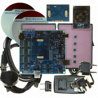
C8051T61 Kit Contents The C8051T61x development kit contains the following items: C8051T610 main board C8051T610 TQFP 32-pin socketed daughter board for programming TQFP devices C8051T610 emulation daughter ...
Page 2
C8051T61x-DK 3.1.2. Third-Party Toolsets The Silicon Laboratories IDE has native support for many 8051 compilers. Natively-supported tools are: Keil IAR Raisonance Tasking Hi-Tech SDCC Please note that the demonstration applications for the C8051T61x development kit are written for the Keil ...
Page 3
The Configuration Wizard utility helps accelerate development by automatically generating initialization source code to configure and enable the on-chip resources needed by most design projects. In just a few steps, the wizard creates complete startup code for a specific Silicon ...
Page 4
C8051T61x- PWR J12 P1 J2 C8051T610 EDB J3 F310 SILICON LABS www.silabs.com P4 J13 Figure 2. Hardware Setup (Emulation Daughter Board) 5. Software Setup The included CD-ROM contains the Silicon Laboratories Integrated Development Environment ...
Page 5
CP210xVCPInstaller.exe complete the installation process, connect the included USB cable between the host computer and the USB connector (P2) on the C8051T610 Target Board. Windows will automatically finish the driver installation. Information windows will pop up from the ...
Page 6
C8051T61x-DK Note: To enable automatic downloading if the program build is successful, select “Enable Automatic Connect/Download after → Build” in the Project Target Build Configuration dialog. If errors occur during the build process, the IDE will not attempt the download. ...
Page 7
J10 Communications Interface Data Signal header J11 VPP supply connection used when programming OTP devices J12 Connects potentiometer to the port pin, P1.2, on the device J13 Additional connections to ground Figure 3. C8051T610 Main Board (Included in Kit) Figure ...
Page 8
C8051T61x-DK Figure 5. C8051T610 Evaluation Daughter Board (Included in Kit) Figure 6. C8051T610 TQFP Socket Daughter Board (Included in Kit) Figure 7. C8051T610 28-Pin QFN Socket Daughter Board (Available Separately) 8 C8051T610 EDB U1 F310 SILICON LABS www.silabs.com C8051T610 LQFP32 ...
Page 9
Figure 8. C8051T610 24-Pin QFN Socket Daughter Board (Available Separately) 8.1. System Clock Sources The C8051T61x devices feature a calibrated internal oscillator that is enabled as the system clock source on reset. After reset, the internal oscillator operates at a ...
Page 10
C8051T61x-DK Table 1 lists the port pins and headers corresponding to the switches, LEDs, and potentiometer. Description SW RESET Green LED labeled "LED" Green LED labeled "USB Active" Red LED labeled "PWR" Red LED connected to VPP Green LED labeled ...
Page 11
Figure 11. J6 and J7 Shorting Block Configuration for Power Using 3.3 V Regulator and P3 Figure 12. J6 and J7 Shorting Block Configuration for External Power Using J1 8.4. USB Debug Adapter (DEBUG / P5) A Universal Serial Bus ...
Page 12
C8051T61x-DK Figure 13. Shorting Block Configuration when Using the CP2103 Figure 14. Shorting Block Configuration when Using the USB Debug Adapter 8.7. PORT I/O Connector (J2, J3, J4, and J5) Each of the C8051T61x's I/O pins, as well as +3VD ...
Page 13
Using Alternate Supplies with the C8051T61x Development Kit For most evaluation purposes, the onboard 3.3 V supply regulator is sufficient to be used as a VDD power supply. However, in applications where a different supply voltage is desired (for ...
Page 14
C8051T61x-DK 9. Schematics 14 Rev. 0.1 ...
Page 15
C8051T61x-DK Rev. 0.1 15 ...
Page 16
C8051T61x-DK 16 Rev. 0.1 ...
Page 17
C8051T61x-DK Rev. 0.1 17 ...
Page 18
C8051T61x-DK 18 Rev. 0.1 ...
Page 19
C8051T61x-DK Rev. 0.1 19 ...
Page 20
... Should Buyer purchase or use Silicon Laboratories products for any such unintended or unauthorized ap- plication, Buyer shall indemnify and hold Silicon Laboratories harmless against all claims and damages. Silicon Laboratories and Silicon Labs are trademarks of Silicon Laboratories Inc. Other products or brandnames mentioned herein are trademarks or registered trademarks of their respective holders. ...