M53015EVB Freescale Semiconductor, M53015EVB Datasheet - Page 7
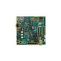
M53015EVB
Manufacturer Part Number
M53015EVB
Description
KIT DEVELOPMENT FOR MCF53015
Manufacturer
Freescale Semiconductor
Type
MPUr
Specifications of M53015EVB
Contents
Board, Cables, Cards, Power Supply Kit
Processor To Be Evaluated
MCF5301
Data Bus Width
32 bit
Interface Type
Ethernet, USB, UART, SPI, I2C
Maximum Operating Temperature
+ 85 C
Minimum Operating Temperature
- 40 C
Operating Supply Voltage
3.6 V
Silicon Manufacturer
Freescale
Core Architecture
Coldfire
Core Sub-architecture
Coldfire V3
Silicon Core Number
MCF53
Silicon Family Name
MCF5301x
Rohs Compliant
Yes
For Use With/related Products
MCF53015
Lead Free Status / RoHS Status
Lead free / RoHS Compliant


5.7
The M53015EVB provides 64 Mbytes of on-board Mobile SDRAM (16bit x 32M Micron Mobile
SDRAM). On-board terminations are provided.
5.8
The M53015EVB provides a BDM (Background Debug Mode) and JTAG Connector (26-pin header), J37,
to give the end-user the ability to utilize the BDM/JTAG features of the MCF53015 processor. In addition,
the M53015EVB provides an on board USB to BDM interface, J48.
5.9
The MCF53015 Processor contains a USB OTG module. This module is USB 2.0 compliant. It supports
host and device modes, and provides an on-chip full-speed/low-speed transceiver. One mini-AB receptacle
(USB 2.0 OTG) is provided on the M53015EVB.
5.10
The MCF53015 Processor contains a USB Host module. This module is USB 2.0 compliant. It supports
host mode only, and provides an on-chip full-speed/low-speed transceiver. One Type-A receptacle (USB
2.0 Host) is provided on the M53015EVB.
5.11
There are four external interrupt pins provided on the MCF53015. IRQ7_B is connected to push button
switch SW1 to provide a user driven ABORT signal. This signal is also connected to the LED D5 to denote
when this signal is asserted.
IRQ1_B and IRQ4_B are available on the University Breakout Connector, J1. IRQ6_B is available on pin
2 of J32. IRQ6_B is also used as the USB_CLKIN line.
5.12
The MCF53015 provides four 32-bit timers with DMA support. DT0 - DT3 are connected to LEDs D1 -
D4. They can be disconnected from the LEDs by removing jumpers H2 - H5.
5.13
The DSPI Module on the MCF53015 is used in SPI bus interface mode to interface with a TI
TLV320AIC23B stereo audio CODEC.
5.14
The MCF53015’s SSI port is connected to the Audio input of the external stereo audio CODEC. These
pins are also available on the University Breakout Connector, J1. Additionally, these pins are muxed with
UART1 and through jumper options, can be connected to an RS232; line driver to be used as UART pins.
Freescale Semiconductor
SDRAM Interface
BDM and JTAG Interfaces — Processor
USB 2.0 Host and Device(OTG)
USB Host Module
Interrupts
Timers
DSPI
SSI Port
M53015 Evaluation Board, Rev. 0.5
7
Related parts for M53015EVB
Image
Part Number
Description
Manufacturer
Datasheet
Request
R

Part Number:
Description:
Manufacturer:
Freescale Semiconductor, Inc
Datasheet:
Part Number:
Description:
Manufacturer:
Freescale Semiconductor, Inc
Datasheet:
Part Number:
Description:
Manufacturer:
Freescale Semiconductor, Inc
Datasheet:
Part Number:
Description:
Manufacturer:
Freescale Semiconductor, Inc
Datasheet:
Part Number:
Description:
Manufacturer:
Freescale Semiconductor, Inc
Datasheet:
Part Number:
Description:
Manufacturer:
Freescale Semiconductor, Inc
Datasheet:
Part Number:
Description:
Manufacturer:
Freescale Semiconductor, Inc
Datasheet:
Part Number:
Description:
Manufacturer:
Freescale Semiconductor, Inc
Datasheet:
Part Number:
Description:
Manufacturer:
Freescale Semiconductor, Inc
Datasheet:
Part Number:
Description:
Manufacturer:
Freescale Semiconductor, Inc
Datasheet:
Part Number:
Description:
Manufacturer:
Freescale Semiconductor, Inc
Datasheet:
Part Number:
Description:
Manufacturer:
Freescale Semiconductor, Inc
Datasheet:
Part Number:
Description:
Manufacturer:
Freescale Semiconductor, Inc
Datasheet:
Part Number:
Description:
Manufacturer:
Freescale Semiconductor, Inc
Datasheet:
Part Number:
Description:
Manufacturer:
Freescale Semiconductor, Inc
Datasheet: