ATEVK1104S Atmel, ATEVK1104S Datasheet - Page 8
ATEVK1104S
Manufacturer Part Number
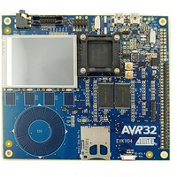
ATEVK1104S
Description
KIT EVAL FOR AT32UC
Manufacturer
Atmel
Series
AVR®32 UC3r
Type
MCUr
Specifications of ATEVK1104S
Contents
Board, Cables
Tool Type
Development Kit
Cpu Core
AVR 32
Data Bus Width
32 bit
Processor Series
AT32
Processor To Be Evaluated
AT32UC3A3256S
Interface Type
USB, JTAG, SD Card, Nexus, MMC
Core Architecture
AVR
Operating Supply Voltage
5.5 V
For Use With/related Products
*
Lead Free Status / RoHS Status
Lead free / RoHS Compliant


3.7 Analyzing filters in the frequency domain
8
AVR32908
Analyzing a signal by FFT:
•
•
•
•
•
•
•
Changing amplitude:
•
•
•
When the amplitude of signal 2 increases above 0.50, some new components may
start to appear. This is caused by signal saturation, an effect we will cover in more
detail in the next hands-on training.
The FFT function is self scaling. When the amplitude of signal 2 is higher than that of
signal 1, the FFT output is scaled. It may appear as if signal 1 decreases in amplitude
as signal 2 starts to define the maximum of the display.
Viewing the frequency domain:
•
•
Turning on low-pass filtering:
•
•
•
High-pass filtering:
•
•
Changing frequency:
•
•
•
Push and hold the BACK button for 3 seconds to reset the signals and filters.
Select the output signal and push FUNC 1 to enable FFT view.
Select signal source 2.
Change the frequency to 4 kHz.
Observe how the signal component seen in the FFT view shifts to the right with
increasing frequency.
Reduce the frequency, and see how the signal component moves to the left.
Zoom in on the output signal to see more details.
Select signal source 2.
Change the amplitude to 0 and observe how the signal component disappears.
Change the amplitude to 0.9999 and observe how the signal component grows
Push and hold the BACK button for 3 seconds to reset the signals and filters.
Select the FFT view for both the combined signal and the output signal
Select the filter.
Enable the low-pass filter.
Observe how the filter allows the 433 Hz of signal 1 to pass though, while the 2
kHz of signal 2 is dampened.
Select the filter and enable the high-pass filter.
Observe how this gives the opposite effect of the low-pass filter.
Set the amplitude of both signal sources to a value in the 0.40 – 0.45 range.
In the FFT view of the combined signal, the two components will have equal
power, but in the filter output only the high frequency component is visible.
Increase the frequency of signal 1.
32138A-AVR32-02/10
Related parts for ATEVK1104S
Image
Part Number
Description
Manufacturer
Datasheet
Request
R

Part Number:
Description:
DEV KIT FOR AVR/AVR32
Manufacturer:
Atmel
Datasheet:

Part Number:
Description:
INTERVAL AND WIPE/WASH WIPER CONTROL IC WITH DELAY
Manufacturer:
ATMEL Corporation
Datasheet:
Part Number:
Description:
Low-Voltage Voice-Switched IC for Hands-Free Operation
Manufacturer:
ATMEL Corporation
Datasheet:
Part Number:
Description:
MONOLITHIC INTEGRATED FEATUREPHONE CIRCUIT
Manufacturer:
ATMEL Corporation
Datasheet:
Part Number:
Description:
AM-FM Receiver IC U4255BM-M
Manufacturer:
ATMEL Corporation
Datasheet:
Part Number:
Description:
Monolithic Integrated Feature Phone Circuit
Manufacturer:
ATMEL Corporation
Datasheet:
Part Number:
Description:
Multistandard Video-IF and Quasi Parallel Sound Processing
Manufacturer:
ATMEL Corporation
Datasheet:
Part Number:
Description:
High-performance EE PLD
Manufacturer:
ATMEL Corporation
Datasheet:
Part Number:
Description:
8-bit Flash Microcontroller
Manufacturer:
ATMEL Corporation
Datasheet:
Part Number:
Description:
2-Wire Serial EEPROM
Manufacturer:
ATMEL Corporation
Datasheet: