32812 Parallax Inc, 32812 Datasheet - Page 4
32812
Manufacturer Part Number
32812
Description
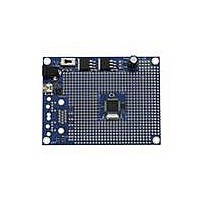
BOARD PROPELLER PROTO USB
Manufacturer
Parallax Inc
Series
Propeller™r
Type
MCUr
Specifications of 32812
Contents
Board
Processor To Be Evaluated
P8X32A-Q44
Interface Type
USB, VGA
Dimensions
7.75 cm x 10.6 cm
Maximum Operating Temperature
+ 80 C
Operating Supply Voltage
6 V to 9 V
Lead Free Status / RoHS Status
Lead free / RoHS Compliant
For Use With/related Products
Propeller Education (PE) Kit
For Use With
122-32000 - MANUAL PROPELLER
Lead Free Status / Rohs Status
Lead free / RoHS Compliant


Add the 100 Ω and 470 Ω Resistors
Add the Norcomp Connector (right)
Add the Servo Circuit (below)
IMPORTANT: Servo Power Supply (Vin)
Use only the Vin jumper setting for powering servos when power is supplied from a 6V battery pack.
Damage could occur to your servos if you use an unregulated power supply.
Note:
on the Propeller Proto Board. If only PS/2 connectors are installed, only the 100 Ω resistors need to be
installed. If only a VGA connector is installed, only the 470 Ω resistors need to be installed.
Copyright © Parallax Inc.
Remove the resistors from their packaging.
Take a 100 Ω resistor (brown-black-brown-gold) and
Place it in the two holes marked 100 right above the
Repeat this process for 3 more 100 Ω resistors
Repeat this process using (3) 470 Ω (yellow-violet-brown-gold); placing each resistor in the 3
Place the Norcomp integrated SVGA and PS/2 mouse and
Solder the signal lines in the four corners (signal lines are the
Once the connector is securely in place and level, solder the
The VGA/mouse/keyboard circuit is now installed.
Solder a 3 pin header into the 3 holes to the right of the 3.3V
Solder the 4 remaining 3 pin headers to the right of the electrolytic
Install the shorting block on the first header to choose the servo
If only video or PS/2 peripherals are needed for an application, standard connectors may be used
bend one lead near the resistor so that it points in
the same direction as the other lead.
Rev A label and solder it in place so the resistor is in
vertical orientation.
moving upwards (you will have 1 spare 100 Ω
resistor left).
sets of holes marked 470.
keyboard connector in the board.
smaller pins).
remaining signal pins, then solder the mechanical pins (the
mechanical pins are the larger pins around the perimeter of the
connector).
regulator.
capacitor.
supply.
Propeller Proto Board (#32212), USB (32812) Accessory Kit (122-32212)
v1.3 2/3/2010 Page 4 of 4
Related parts for 32812
Image
Part Number
Description
Manufacturer
Datasheet
Request
R


Part Number:
Description:
Microcontroller Modules & Accessories DISCONTINUED BY PARALLAX
Manufacturer:
Parallax Inc

Part Number:
Description:
BOOK UNDERSTANDING SIGNALS
Manufacturer:
Parallax Inc
Datasheet:


Part Number:
Description:
COMPETITION RING FOR SUMOBOT
Manufacturer:
Parallax Inc
Datasheet:


Part Number:
Description:
TEXT INFRARED REMOTE FOR BOE-BOT
Manufacturer:
Parallax Inc
Datasheet:
Part Number:
Description:
BOARD EXPERIMENT+LCD NX-1000
Manufacturer:
Parallax Inc
Datasheet:

Part Number:
Description:
CONTROLLER 16SERVO MOTOR CONTROL
Manufacturer:
Parallax Inc
Datasheet:

Part Number:
Description:
BASIC STAMP LOGIC ANALYZER
Manufacturer:
Parallax Inc
Datasheet:

Part Number:
Description:
IC MCU 2K FLASH 50MHZ SO-18
Manufacturer:
Parallax Inc
Datasheet: