DEMO908JL16E Freescale Semiconductor, DEMO908JL16E Datasheet
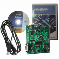
DEMO908JL16E
Specifications of DEMO908JL16E


Related parts for DEMO908JL16E

DEMO908JL16E Summary of contents
Page 1
...
Page 2
...
Page 3
DEMO908JL16 Demonstration Board for Freescale MC68HC908JL16 Family (32-Pin SDIP) User’s Manual Copyright © 2006 SofTec Microsystems Revision 1.0 ® DC01037 ...
Page 4
... THEREOF. Trademarks SofTec Microsystems is a registered trademark of SofTec Microsystems, Spa. Freescale™ and the Freescale logo are trademarks of Freescale Semiconductor, Inc. Microsoft and Windows are trademarks or registered trademarks of Microsoft Corporation registered trademark of International Business Machines Corporation. Other products and company names listed are trademarks or trade names of their respective companies. ...
Page 5
Contents 1 Introduction 5 1.1 Overview 5 1.2 Package Contents 5 1.3 Supported Devices 5 1.4 Recommended Reading 5 1.5 Getting Technical Support 6 2 Hardware Features 7 2.1 Demonstration Board Features 7 3 Software Setup 9 3.1 Overview 9 ...
Page 6
...
Page 7
Introduction 1.1 Overview The DEMO908JL16 Demonstration board has been designed for the evaluation, demonstration and the debugging of the Freescale MC68HC908JL16 microcontroller. The DEMO908JL16 can be used as a standalone application, or via its built-in USB-to-MON08 bridge, or together ...
Page 8
Introduction 1.5 Getting Technical Support Technical assistance is provided to all customers. For technical assistance, documentation and information about products and services, please refer to your local SofTec Microsystems partner. SofTec Microsystems offers its customers a technical support service at ...
Page 9
Hardware Features 2.1 Demonstration Board Features The DEMO908JL16 board features MCU section containing: An MC68HC908JL16 microcontroller (in 32-pin SDIP package, already programmed with a demo application—in addition, you can also use any other pin- to-pin-compatible device); One ...
Page 10
Hardware Features 7. An RS-232 section providing one RS-232 channel connected to the microcontroller’s SCI serial communication interface. The microcontroller’s PTD6/TxD and PTD7/RxD lines are used by the RS-232 channel accelerometer section featuring a Freescale MMA7260Q sensor. All ...
Page 11
Software Setup 3.1 Overview Note: before connecting the Demonstration Board to the PC recommended that you install all of the required software first (see below), so that the appropriate USB driver will be automatically found by ...
Page 12
Software Setup 3.4 Installing SofTec Microsystems Additional Components The SofTec Microsystems Additional Components install all of the other required components to your hard drive. These components include: The Demonstration Board’s USB driver; The software plug-in for CodeWarrior; Examples; Demonstration Board’s ...
Page 13
Hardware Setup 4.1 First Connection The Demonstration Board is connected to a host PC through a USB port. Connection steps are listed below in the recommended flow order: 1. Install all the required system software as described in the ...
Page 14
Hardware Setup Click the “Next >” button. 7. Depending on your Windows settings, the following warning may appear. Note: this warning is related to the fact that the USB driver used by i the Demonstration Board is not digitally signed ...
Page 15
Click the “Finish” button to exit from the “Found New Hardware Wizard” procedure. 9. The Demonstration Board’s USB driver is now installed on your system. 4.2 Power Supply The Demonstration Board can be powered in three ways ...
Page 16
Hardware Setup “POWER SEL1” “POWER SEL2” “USB” “3V3 OUT” “5V IN” Removed “UNREG” “3V3 OUT” “5V IN” Removed Removed “3V3 OUT” “5V IN” Removed Page 14 Configuration Selected Power supply taken from the USB connector. 3.3 V supplied to the ...
Page 17
Operating Modes 5.1 Overview The Demonstration Board can work in two modes: “standalone” mode and “host” mode. 5.2 Standalone Mode In standalone mode connection is required. The microcontroller is factory programmed with a sample application. To run ...
Page 18
Operating Modes Note: all of the HC08 family devices feature a monitor code resident in i ROM which, through a serial communication line, allows the programming and the in-circuit debugging of the user application. The monitor code is executed in ...
Page 19
Application Tutorial 6.1 Overview This section will provide a step-by-step guide on how to launch your first project and get started with the CodeWarrior for HC(S)08 user interface. 6.2 Step-by-Step Tutorial The sample application is the same as the ...
Page 20
...
Page 21
Summary of Jumper and Connector Settings 7.1 Jumpers Name Reference J302 J102 J101 J205 J207 J206 Description/Pinout See chapter “4.2 Power Supply” for details OSCILLATOR ENABLE Installed: On-board crystal selected (default) Not Installed: ...
Page 22
Summary of Jumper and Connector Settings Name Reference J202 J203 J204 1 J402 1 7.2 Connectors Name Reference J301 2 1 Page 20 Description/Pinout LED0 ENABLE Installed: The LED0 is connected to the PTD4 port of the microcontroller (default) Not ...
Page 23
Name Reference J201 J401 Description/Pinout RS-232 Connector 1. N. N.C. 5. GND 6. N.C. 7. N.C. 8. N.C. 9. N.C. USB Connector USB Bus Power Supply Line ...
Page 24
Summary of Jumper and Connector Settings Name Reference J103 Page 22 Description/Pinout ...
Page 25
Name Reference J104 Description/Pinout MON08 Connector (Not Populated) 1. N.C. 2. VSS 3. N.C. 4. RST# 5. N.C. 6. IRQ# 7. N.C. 8. N.C. ...
Page 26
...
Page 27
Troubleshooting 8.1 USB Driver Problems If you connected the Demonstration Board to the PC before installing the SofTec Microsystems Additional Components, the Demonstration Board’s USB driver may not have been correctly installed on your system. Unplugging and replugging the ...
Page 28
...
Page 29
...
Page 30
...
Page 31
...
Page 32
...