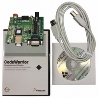
DEMO9S08SG8 Freescale Semiconductor, DEMO9S08SG8 Datasheet

DEMO9S08SG8
Specifications of DEMO9S08SG8
Related parts for DEMO9S08SG8
DEMO9S08SG8 Summary of contents
Page 1
DEMO9S08SH8/SG8 Demonstration Board for Freescale MC9S08SH8/SG8 Axiom Manufacturing • 2813 Industrial Lane • Garland, TX 75041 Email: Sales@axman.com Web: http://www.axman.com ...
Page 2
CAUTIONARY NOTES ..............................................................................................................4 TERMINOLOGY.........................................................................................................................4 FEATURES ................................................................................................................................5 REFERENCES ...........................................................................................................................6 GETTING STARTED..................................................................................................................6 OPERATING MODES ................................................................................................................6 RUN MODE ........................................................................................................................... 6 DEBUG MODE ...................................................................................................................... 7 MEMORY MAP ..........................................................................................................................7 SOFTWARE DEVELOPMENT...................................................................................................8 DEVELOPMENT SUPPORT ......................................................................................................8 INTEGRATED BDM ...
Page 3
Figure 1: BDM_PORT Header....................................................................................................9 Figure 2: PWR_SEL Option Header .........................................................................................10 Figure 3: VX_EN Option Header ..............................................................................................11 Figure 4: COM Connector.........................................................................................................12 ...
Page 4
CAUTIONARY NOTES 1) Electrostatic Discharge (ESD) prevention measures should be used when handling this product. ESD damage is not a warranty repair item. 2) Axiom Manufacturing does not assume any liability ...
Page 5
FEATURES The DEMO9S08SH8/SG8 is a demonstration board for the MC9S08SH8 or the MC9S08SG microcontroller. Application development is quick and easy ...
Page 6
REFERENCES Reference documents are provided on the support CD in Acrobat Reader format. DEMO9S08SH8_UG.pdf DEMO9S08SH8_QSG.pdf DEMO9S08SH8 _SCH_A.pdf DEMO9S08SH8_Silk_A.pdf SH8DEMO.zip GETTING ...
Page 7
The programmed application will begin to execute. Debug Mode Debug Mode supports application development and debug. Debug mode is available to the user through the integrated USB-Multilink BDM or through ...
Page 8
Table 3: Memory Map $0000 - Direct Page $007F REGISTERS $0080 - RAM $027F $0280 - Unimplemented $17FF $1800 - ...
Page 9
BDM_PORT Header A compatible HCS12 BDM cable can also attach to the 6-pin BDM interface header (BDM_PORT). This header is ...
Page 10
Figure 2: PWR_SEL Option Header Selects power input from USB-BDM PWR_SEL Selects power input ...
Page 11
Figure 3: VX_EN Option Header Enabled VX_EN CAUTION: Do not exceed available current supply from USB-Multilink BDM or on-board regu- lator, when sourcing power through connector J1 to ...
Page 12
RS-232 An RS-232 translator provides RS-232 to TTL/CMOS logic level translation on the COM con- nector. The COM connector is a 9-pin Dsub, right-angle connector. A ferrite bead on shield ground ...
Page 13
USER I/O User I/O includes 1 potentiometers, 1 Light Sensor, 2 push button switches, and 2 green LEDs for user ...
Page 14
User Enable The User option header block enables or disables each User I/O device individually. User I/O includes 4 green LEDs, 2 push button switches, one 4-position DIP switch, a Light ...


