DEMO9S08SG32AUTO Freescale Semiconductor, DEMO9S08SG32AUTO Datasheet - Page 7
DEMO9S08SG32AUTO
Manufacturer Part Number
DEMO9S08SG32AUTO
Description
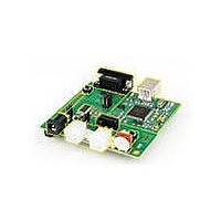
DEMO BOARD FOR MC9S08SG32
Manufacturer
Freescale Semiconductor
Type
MCUr
Specifications of DEMO9S08SG32AUTO
Contents
*
Processor To Be Evaluated
MC9S08Sx
Data Bus Width
8 bit
Interface Type
RS-232, USB
Silicon Manufacturer
Freescale
Core Architecture
HCS08
Core Sub-architecture
HCS08
Silicon Core Number
MC9S08
Silicon Family Name
S08SG
Kit Contents
Board
Rohs Compliant
Yes
For Use With/related Products
MC9S08SG32
Lead Free Status / RoHS Status
Lead free / RoHS Compliant


U S E R
3. Apply power to the board.
4. The programmed application will begin to execute.
Debug Mode
Debug Mode supports application development and debug. Debug mode is available to the
user through the integrated USB-Multilink BDM or through the use of an external
HCS12/HCS08 BDM cable. Use of the integrated USB-Multilink BDM requires only a host PC
with an available USB port and an A/B type USB cable. A 6-pin BDM interface header
(BDM_PORT) supports the use of an external HCS08/HCS12 BDM cable. The BDM_PORT
header is not installed in default configuration. The steps below describe using the integrated
USB-Multilink BDM.
1. Connect auxiliary equipment to board as required by application.
2. Install and launch CodeWarrior Development Studio, or P&E PKGHCS08Z tool set.
3. Configure the board option jumpers for DEBUG mode.
Table 2: BDM Mode Setup
4. Connect the supplied USB cable between an available USB port on the host PC and the
5. Hosting development software will establish DEBUG communication.
6. Refer to BDM cable documentation for details on use of BDM.
MEMORY MAP
The table below shows the default memory map for the MC9S08SH32/SG32 immediately out
of reset. Refer to the MC9S08SH32/SG32 Data Sheet (DS) for further information.
NOTE: See Power section below to configure power input from PWR connector or from J1 connector.
NOTE: Refer to the Development Support section below for details on using an external HCS12 BDM cable.
USB connector on the board.
PWR_SEL
COM_SEL
VX_EN
USER
LIN_EN
G U I D E
Pin1 – Pin2 (VB)
As Required
As Required
As Required
As Required
7
Related parts for DEMO9S08SG32AUTO
Image
Part Number
Description
Manufacturer
Datasheet
Request
R

Part Number:
Description:
Manufacturer:
Freescale Semiconductor, Inc
Datasheet:
Part Number:
Description:
Manufacturer:
Freescale Semiconductor, Inc
Datasheet:
Part Number:
Description:
Manufacturer:
Freescale Semiconductor, Inc
Datasheet:
Part Number:
Description:
Manufacturer:
Freescale Semiconductor, Inc
Datasheet:
Part Number:
Description:
Manufacturer:
Freescale Semiconductor, Inc
Datasheet:
Part Number:
Description:
Manufacturer:
Freescale Semiconductor, Inc
Datasheet:
Part Number:
Description:
Manufacturer:
Freescale Semiconductor, Inc
Datasheet:
Part Number:
Description:
Manufacturer:
Freescale Semiconductor, Inc
Datasheet:
Part Number:
Description:
Manufacturer:
Freescale Semiconductor, Inc
Datasheet:
Part Number:
Description:
Manufacturer:
Freescale Semiconductor, Inc
Datasheet:
Part Number:
Description:
Manufacturer:
Freescale Semiconductor, Inc
Datasheet:
Part Number:
Description:
Manufacturer:
Freescale Semiconductor, Inc
Datasheet:
Part Number:
Description:
Manufacturer:
Freescale Semiconductor, Inc
Datasheet:
Part Number:
Description:
Manufacturer:
Freescale Semiconductor, Inc
Datasheet:
Part Number:
Description:
Manufacturer:
Freescale Semiconductor, Inc
Datasheet: