DEMO9S08SH32 Freescale Semiconductor, DEMO9S08SH32 Datasheet - Page 10
DEMO9S08SH32
Manufacturer Part Number
DEMO9S08SH32
Description
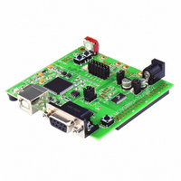
DEMO BOARD FOR MC9S08SH32
Manufacturer
Freescale Semiconductor
Type
MCUr
Datasheets
1.DEMO9S08SG32AUTO.pdf
(15 pages)
2.DEMO9S08SG32AUTO.pdf
(2 pages)
3.DEMO9S08SH32.pdf
(1 pages)
Specifications of DEMO9S08SH32
Contents
*
Processor To Be Evaluated
MC9S08SH16 and MC9S08SH32
Data Bus Width
8 bit
Interface Type
RS-232, USB
Silicon Manufacturer
Freescale
Core Architecture
HCS08
Core Sub-architecture
HCS08
Silicon Core Number
MC9S08
Silicon Family Name
S08SH
Kit Contents
Board
Rohs Compliant
Yes
For Use With/related Products
MC9S08SH16, MC9S08SH32
Lead Free Status / RoHS Status
Lead free / RoHS Compliant


D E M O 9 S 0 8 S H 3 2 / S G 3 2
U S E R
Figure 2: PWR_SEL Option Header
Power from the integrated BDM is drawn from the USB bus and is limited to 500 mA. This
current limit accounts for the total current supplied over the USB cable to the BDM circuit, the
target board, and any connected circuitry. Current drain in excess of 500 mA will violate the
USB specification and will cause the USB bus to disconnect. This will cause the board to
exhibit power cycling where the board appears to turn-on then off continually. Damage to the
host PC or the target board may also result.
The on-board voltage regulator (VR1) accepts power input through a 2.0mm barrel connector
(PWR). Input voltage may range from +6V to +18V. The voltage regulator (VR1) provides a
+5V fixed output limited to 250mA. Over-temperature and over-current limit built into the
voltage regulator provides protection from excessive stress. The user should consider the
maximum output current limit of VR1 when attempting to power off-board circuitry through
connector J1.
If powered from the PWR connector, the integrated BDM may still be used to develop and
debug application code. Alternately, the board may be powered from the integrated BDM
while the LIN bus is powered from the PWR connector.
VX_EN
The VX_EN option header is a 2-pin jumper that connects or disconnects input J1-1 directly to
the target board, +5V voltage rail. J1-3 is directly connected to the ground plane. Use of this
feature requires a regulated +5V input power source.
minimize noise but is not regulated. Care should be exercised when using this feature; no
protection is applied on this input and damage to the target board may result if over-driven.
Also, do not attempt to power the target board through this connector while also applying
power through the USB-Multilink BDM or the PWR connector; damage to the board may result.
Power may also be sourced to off-board circuitry through the J1 connector. The current
supplied from the USB bus or the on-board regulator limits current available to external
circuitry. Excessive current drain may damage the target board, the host PC USB hub, or the
on-board regulator. The figure below details the VX_EN header connections.
G U I D E
NOTE: Set PWR_SEL jumper to VB during application development. Use barrel connector
PWR_SEL
PWR_SEL
1
1
input (PWR) to support LIN functionality if needed.
2
2
3
3
Selects power input from USB-BDM
Selects power input from on-board regulator or J1
10
This power input is decoupled to
J U L Y
9 ,
2 0 0 7
Related parts for DEMO9S08SH32
Image
Part Number
Description
Manufacturer
Datasheet
Request
R

Part Number:
Description:
Manufacturer:
Freescale Semiconductor, Inc
Datasheet:
Part Number:
Description:
Manufacturer:
Freescale Semiconductor, Inc
Datasheet:
Part Number:
Description:
Manufacturer:
Freescale Semiconductor, Inc
Datasheet:
Part Number:
Description:
Manufacturer:
Freescale Semiconductor, Inc
Datasheet:
Part Number:
Description:
Manufacturer:
Freescale Semiconductor, Inc
Datasheet:
Part Number:
Description:
Manufacturer:
Freescale Semiconductor, Inc
Datasheet:
Part Number:
Description:
Manufacturer:
Freescale Semiconductor, Inc
Datasheet:
Part Number:
Description:
Manufacturer:
Freescale Semiconductor, Inc
Datasheet:
Part Number:
Description:
Manufacturer:
Freescale Semiconductor, Inc
Datasheet:
Part Number:
Description:
Manufacturer:
Freescale Semiconductor, Inc
Datasheet:
Part Number:
Description:
Manufacturer:
Freescale Semiconductor, Inc
Datasheet:
Part Number:
Description:
Manufacturer:
Freescale Semiconductor, Inc
Datasheet:
Part Number:
Description:
Manufacturer:
Freescale Semiconductor, Inc
Datasheet:
Part Number:
Description:
Manufacturer:
Freescale Semiconductor, Inc
Datasheet:
Part Number:
Description:
Manufacturer:
Freescale Semiconductor, Inc
Datasheet: