YRDKSH7216 Renesas Electronics America, YRDKSH7216 Datasheet - Page 13
YRDKSH7216
Manufacturer Part Number
YRDKSH7216
Description
BOARD DEVELOPMENT FOR SH7216
Manufacturer
Renesas Electronics America
Type
MCUr
Specifications of YRDKSH7216
Design Resources
RDK for SH7216 Schematics
Contents
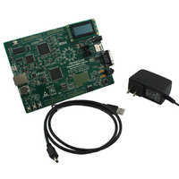
Board, Cable, Documentation, Power Supply
For Use With/related Products
SH7216
Lead Free Status / RoHS Status
Lead free / RoHS Compliant


6.1. Switches
There are four switches located on the CPU board. The function of each switch and its connection are shown in Table
6-1.
*Refer to schematic for detailed connectivity information.
6.2. Debug LCD Module
A debug LCD module is supplied on the RDK. The debug LCD module uses a 4-bit interface to reduce the pin allocation.
No contrast control is provided; this is set by a resistor on the RDK. The module supplied with the RDK only supports 5V
operation.
SW1
SW2 (RESET)
SW3*
SW4*
SW5*
SW6
Switch
Mode/Debug Switch – Refer to Table 7-1 for details
When pressed, the RDK microcontroller is reset.
Connects to the Non-Maskable Interrupt (NMI) line.
Connects to an IRQ line for user controls.
Connects to an IRQ input for user controls.
The switch is also used in conjunction with the RES switch to place the device
in BOOT mode when not using the E10A debugger.
E10A Mode Switch – This switch allows the user to reprogram the firmware for
the E10A debugger. In normal mode, the switch should be placed in the
direction shown by the arrow on the PCB, away from the board edge. Refer to
Chapter 8 for details on reprogramming the E10A.
Chapter 6. User Circuitry
Table 6-1: Switch Functions
Function
9
See section 7
RESn, Pin 133
NMI, Pin 123
IRQ5, Pin 10
(Port B, pin 5)
IRQ0, Pin 77
(Port D pin 16)
N/A
Microcontroller
Related parts for YRDKSH7216
Image
Part Number
Description
Manufacturer
Datasheet
Request
R

Part Number:
Description:
KIT STARTER FOR M16C/29
Manufacturer:
Renesas Electronics America
Datasheet:

Part Number:
Description:
KIT STARTER FOR R8C/2D
Manufacturer:
Renesas Electronics America
Datasheet:

Part Number:
Description:
R0K33062P STARTER KIT
Manufacturer:
Renesas Electronics America
Datasheet:

Part Number:
Description:
KIT STARTER FOR R8C/23 E8A
Manufacturer:
Renesas Electronics America
Datasheet:

Part Number:
Description:
KIT STARTER FOR R8C/25
Manufacturer:
Renesas Electronics America
Datasheet:

Part Number:
Description:
KIT STARTER H8S2456 SHARPE DSPLY
Manufacturer:
Renesas Electronics America
Datasheet:

Part Number:
Description:
KIT STARTER FOR R8C38C
Manufacturer:
Renesas Electronics America
Datasheet:

Part Number:
Description:
KIT STARTER FOR R8C35C
Manufacturer:
Renesas Electronics America
Datasheet:

Part Number:
Description:
KIT STARTER FOR R8CL3AC+LCD APPS
Manufacturer:
Renesas Electronics America
Datasheet:
Part Number:
Description:
KIT STARTER FOR RX610
Manufacturer:
Renesas Electronics America
Datasheet:

Part Number:
Description:
KIT STARTER FOR R32C/118
Manufacturer:
Renesas Electronics America
Datasheet:

Part Number:
Description:
KIT DEV RSK-R8C/26-29
Manufacturer:
Renesas Electronics America
Datasheet:

Part Number:
Description:
KIT STARTER FOR SH7124
Manufacturer:
Renesas Electronics America
Datasheet:

Part Number:
Description:
KIT STARTER FOR H8SX/1622
Manufacturer:
Renesas Electronics America
Datasheet:

Part Number:
Description:
KIT DEV FOR SH7203
Manufacturer:
Renesas Electronics America
Datasheet: