DK-VIDEO-4SGX230N Altera, DK-VIDEO-4SGX230N Datasheet - Page 47
DK-VIDEO-4SGX230N
Manufacturer Part Number
DK-VIDEO-4SGX230N
Description
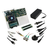
VIDEO KIT STRATIX IV EP4SGX230
Manufacturer
Altera
Series
Stratix® IVr
Type
FPGAr
Datasheet
1.DK-VIDEO-4SGX230N.pdf
(58 pages)
Specifications of DK-VIDEO-4SGX230N
Contents
Board, Daughter Card, Cables, CD, DVD, Power Supply
Silicon Manufacturer
Altera
Core Architecture
FPGA
Core Sub-architecture
Stratix
Silicon Core Number
EP4S
Silicon Family Name
Stratix IV GX
Rohs Compliant
Yes
For Use With/related Products
EP4SGX230K
Lead Free Status / RoHS Status
Lead free / RoHS Compliant
Other names
544-2602


Chapter 6: Board Test System
The Clock Control
Calculating Power
The Clock Control
© November 2009 Altera Corporation
f
The Power Monitor calculates power by measuring two different voltages with the
LT2418 A/D and applying the equation P = V × I to determine the power
consumption. The LT2418 measures the voltage after the appropriate sense resistor
(Vsense) and the voltage drop across that sense resistor (Vdif). The current (I) is
calculated by dividing the measured voltage drop across the resistor by the value of
the sense resistor (I = Vdif/R). Through substitution, the equation for calculating
power becomes P = V × I = Vsense × (Vdif/R) = (Vsense) × (Vdif) × (1/.003).
You can verify the power numbers shown in the Power Monitor with a digital
multimeter that is capable of measuring microvolts to ensure you have enough
significant digits for an accurate calculation. Measure the voltage on one side of the
resistor (the side opposite the power source) and then measure the voltage on the
other side. The first measurement is Vsense and the difference between the two
measurements is Vdif. Plug the values into the equation to determine the power
consumption.
The Clock Control sets the Si570 programmable oscillator to any frequency between
10 MHz and 810 MHz with eight digits of precision to the right of the decimal point.
The oscillator drives a 2-to-4 buffer that drives a copy of the clock to all four edges of
the FPGA.
The Clock Control runs as a stand-alone application. ClockControl.exe resides in the
<install dir>\kits\stratixIVGX_4sgx230_av\examples\board_test_system directory.
On Windows, click Start > All Programs > Altera > Audio Video Development Kit,
Stratix IV GX Edition <version> > Clock Control to start the application.
For more information about the Si570 and the Stratix IV GX development board’s
clocking circuitry and clock input pins, refer to the
Board Reference
The Clock Control communicates with the MAX II device on the board through the
JTAG bus. The Si570 programmable oscillator is connected to the MAX II device
through a 2-wire serial bus.
Manual.
Figure 6–13
shows the Clock Control.
Audio Video Development Kit, Stratix IV GX Edition User Guide
Stratix IV GX FPGA Development
6–25
Related parts for DK-VIDEO-4SGX230N
Image
Part Number
Description
Manufacturer
Datasheet
Request
R


Part Number:
Description:
VIDEO KIT W/CYCLONE II EP2C70N
Manufacturer:
Altera
Datasheet:

Part Number:
Description:
CYCLONE II STARTER KIT EP2C20N
Manufacturer:
Altera
Datasheet:


Part Number:
Description:
CPLD, EP610 Family, ECMOS Process, 300 Gates, 16 Macro Cells, 16 Reg., 16 User I/Os, 5V Supply, 35 Speed Grade, 24DIP
Manufacturer:
Altera Corporation
Datasheet:
Part Number:
Description:
CPLD, EP610 Family, ECMOS Process, 300 Gates, 16 Macro Cells, 16 Reg., 16 User I/Os, 5V Supply, 15 Speed Grade, 24DIP
Manufacturer:
Altera Corporation
Datasheet:
Part Number:
Description:
Manufacturer:
Altera Corporation
Datasheet:
Part Number:
Description:
CPLD, EP610 Family, ECMOS Process, 300 Gates, 16 Macro Cells, 16 Reg., 16 User I/Os, 5V Supply, 30 Speed Grade, 24DIP
Manufacturer:
Altera Corporation
Datasheet:
Part Number:
Description:
High-performance, low-power erasable programmable logic devices with 8 macrocells, 10ns
Manufacturer:
Altera Corporation
Datasheet:
Part Number:
Description:
High-performance, low-power erasable programmable logic devices with 8 macrocells, 7ns
Manufacturer:
Altera Corporation
Datasheet:
Part Number:
Description:
Classic EPLD
Manufacturer:
Altera Corporation
Datasheet:
Part Number:
Description:
High-performance, low-power erasable programmable logic devices with 8 macrocells, 10ns
Manufacturer:
Altera Corporation
Datasheet:
Part Number:
Description:
Manufacturer:
Altera Corporation
Datasheet:
Part Number:
Description:
Manufacturer:
Altera Corporation
Datasheet: