R0K564112S000BE#WS Renesas Electronics America, R0K564112S000BE#WS Datasheet - Page 5
R0K564112S000BE#WS
Manufacturer Part Number
R0K564112S000BE#WS
Description
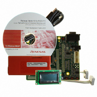
DEV EVALUATION KIT R32C/111
Manufacturer
Renesas Electronics America
Series
R32r
Type
MCUr
Datasheets
1.R0K564112S000BEWS.pdf
(37 pages)
2.R0K564112S000BEWS.pdf
(6 pages)
3.R0K564112S000BEWS.pdf
(13 pages)
4.R0K564112S000BEWS.pdf
(23 pages)
Specifications of R0K564112S000BE#WS
Contents
CPU Board, LCD Display Module, E8 Emulator, Cable, QuickStart Guide and CD-ROM
For Use With/related Products
R32C/111
Lead Free Status / RoHS Status
Lead free / RoHS Compliant


Table of Contents
Chapter 1. Preface .................................................................................................................................................. 1
Chapter 2. Purpose ................................................................................................................................................. 2
Chapter 3. Power Supply ........................................................................................................................................ 3
Chapter 4. Board Layout ......................................................................................................................................... 4
Chapter 5. Block Diagram ....................................................................................................................................... 6
Chapter 6. User Circuitry ......................................................................................................................................... 7
Chapter 7. Modes .................................................................................................................................................. 17
Chapter 8. Programming Methods ........................................................................................................................ 18
Chapter 9. Headers ............................................................................................................................................... 19
Chapter 10. Code Development ........................................................................................................................... 26
Chapter 11. Component Placement ...................................................................................................................... 29
Chapter 12. Additional Information ........................................................................................................................ 30
3.1. Requirements ............................................................................................................................................... 3
3.2. Power–up Behaviour .................................................................................................................................... 3
4.1. Component Layout ....................................................................................................................................... 4
4.2. Board Dimensions ........................................................................................................................................ 5
6.1. Switches ....................................................................................................................................................... 7
6.2. LEDs ............................................................................................................................................................. 7
6.3. Potentiometer ............................................................................................................................................... 7
6.4. Serial port ..................................................................................................................................................... 7
6.5. Debug LCD Module ...................................................................................................................................... 8
6.6. Option Links .................................................................................................................................................. 8
6.7. Oscillator Sources ...................................................................................................................................... 15
6.8. Reset Circuit ............................................................................................................................................... 15
7.1. Boot mode .................................................................................................................................................. 17
7.2. User Mode .................................................................................................................................................. 17
9.1. Microcontroller Ring Headers ..................................................................................................................... 19
9.2. Application Headers ................................................................................................................................... 23
10.1. Overview ................................................................................................................................................... 26
10.2. Compiler Restrictions ............................................................................................................................... 26
10.3. Breakpoint Support ................................................................................................................................... 26
10.4. Memory Map ............................................................................................................................................. 27
iii
Related parts for R0K564112S000BE#WS
Image
Part Number
Description
Manufacturer
Datasheet
Request
R

Part Number:
Description:
KIT STARTER FOR M16C/29
Manufacturer:
Renesas Electronics America
Datasheet:

Part Number:
Description:
KIT STARTER FOR R8C/2D
Manufacturer:
Renesas Electronics America
Datasheet:

Part Number:
Description:
R0K33062P STARTER KIT
Manufacturer:
Renesas Electronics America
Datasheet:

Part Number:
Description:
KIT STARTER FOR R8C/23 E8A
Manufacturer:
Renesas Electronics America
Datasheet:

Part Number:
Description:
KIT STARTER FOR R8C/25
Manufacturer:
Renesas Electronics America
Datasheet:

Part Number:
Description:
KIT STARTER H8S2456 SHARPE DSPLY
Manufacturer:
Renesas Electronics America
Datasheet:

Part Number:
Description:
KIT STARTER FOR R8C38C
Manufacturer:
Renesas Electronics America
Datasheet:

Part Number:
Description:
KIT STARTER FOR R8C35C
Manufacturer:
Renesas Electronics America
Datasheet:

Part Number:
Description:
KIT STARTER FOR R8CL3AC+LCD APPS
Manufacturer:
Renesas Electronics America
Datasheet:
Part Number:
Description:
KIT STARTER FOR RX610
Manufacturer:
Renesas Electronics America
Datasheet:

Part Number:
Description:
KIT STARTER FOR R32C/118
Manufacturer:
Renesas Electronics America
Datasheet:

Part Number:
Description:
KIT DEV RSK-R8C/26-29
Manufacturer:
Renesas Electronics America
Datasheet:

Part Number:
Description:
KIT STARTER FOR SH7124
Manufacturer:
Renesas Electronics America
Datasheet:

Part Number:
Description:
KIT STARTER FOR H8SX/1622
Manufacturer:
Renesas Electronics America
Datasheet:

Part Number:
Description:
KIT DEV FOR SH7203
Manufacturer:
Renesas Electronics America
Datasheet: