ICE4000 Microchip Technology, ICE4000 Datasheet - Page 23
ICE4000
Manufacturer Part Number
ICE4000
Description
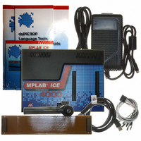
EMULATOR MPLAB-ICE 4000 POD
Manufacturer
Microchip Technology
Series
MPLAB® ICE 4000r
Type
Microcontrollerr
Datasheet
1.ICE4000.pdf
(98 pages)
Specifications of ICE4000
Contents
ICE4000 POD, Parallel and USB Cable, Power Supply, MPLAB IDE CD and Documentation
Interface Type
USB
Lead Free Status / RoHS Status
Contains lead / RoHS non-compliant
For Use With/related Products
dsPIC30F & PIC18 Series
Lead Free Status / Rohs Status
Lead free / RoHS Compliant


3.6
2004 Microchip Technology Inc.
SETTING UP THE PROCESSOR CLOCK
3.5.3
MPLAB ICE 4000 also supports LOW VOLTAGE emulation down to 2.5V. The emulator
system cannot provide any voltage level other than 5V to the emulator processor. In
this configuration, power must be supplied by the target board (see Section 3.5.2
“Processor Power from Target Board”).
Before using low voltage, check the limitations for your selected device. Some devices
allow emulator pins to come up as output high, instead of input. Make certain you do
not allow the emulated device to do this if your application cannot tolerate 5V.
MPLAB ICE 4000 can use the on-board clock with either emulator or target power, or
it can use the target board clock with target board power.
3.6.1
MPLAB ICE 4000 has an on-board clock that can be programmed to a frequency
between 32 kHz and 100 MHz. Refer to the specific device's data sheet to determine
the supported frequency range.
1. Select an Oscillator Type (Section 3.3.3 “Oscillator Settings”).
2. Select the Clock tab on the Debugger>Settings dialog.
3. Select the Desired Frequency magnitude (MHz, kHz or Hz) and enter the
4. Click Apply.
The clock will be programmed to operate as close to the entered frequency as possible.
Since the generated clock frequency will be slightly different than the desired clock
frequency, the Actual Frequency will be displayed. The Actual Frequency will be within
0.5% of the desired frequency.
3.6.1.1
If the Oscillator mode has a HW PLL associated with it, the run time frequency will be
the desired frequency. Example: To emulate a target with a 5 MHz HS crystal while
using HW PLL mode, set the desired frequency to 20 MHz.
For parts (e.g., PIC18F8680) that support SW enabled PLL, please do not enter a
frequency that, when multiplied by 4, would go over the maximum speed the emulator
supports.
Consult the device limitations to see how PLL is emulated for your selected device.
3.6.1.2
To verify the clock frequency, you can set up a complex trigger and then measure the
trigger output pulse width (one instruction cycle) of the TRIGOUT logic probe
(Section B.7 “Logic Probes”) in frequency and multiply by 4.
Desired Frequency. Refer to the specific device’s data sheet to determine the
supported frequency range for each oscillator type.
Note: If you enter a frequency that is out of range, your system will not
Low Voltage Emulation
Using the On-board Clock
PLL
VERIFY FREQUENCY
operate properly.
General Set Up
DS51490A-page 17
Related parts for ICE4000
Image
Part Number
Description
Manufacturer
Datasheet
Request
R

Part Number:
Description:
IC USB FOR USB2WIGGLER 14PIN
Manufacturer:
Macraigor Systems LLC
Part Number:
Description:
IC USB FOR USB2DEMOM 14PIN
Manufacturer:
Macraigor Systems LLC
Datasheet:

Part Number:
Description:
Manufacturer:
Microchip Technology Inc.
Datasheet:
Part Number:
Description:
Manufacturer:
Microchip Technology Inc.
Datasheet:
Part Number:
Description:
Manufacturer:
Microchip Technology Inc.
Datasheet:
Part Number:
Description:
Manufacturer:
Microchip Technology Inc.
Datasheet:
Part Number:
Description:
Manufacturer:
Microchip Technology Inc.
Datasheet:
Part Number:
Description:
Manufacturer:
Microchip Technology Inc.
Datasheet:
Part Number:
Description:
Manufacturer:
Microchip Technology Inc.
Datasheet:
Part Number:
Description:
Manufacturer:
Microchip Technology Inc.
Datasheet: