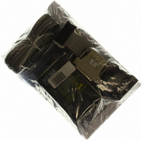
ER3-1M TechTools, ER3-1M Datasheet - Page 7

ER3-1M
Manufacturer Part Number
ER3-1M
Description
EMULATOR EPROM ECONOROM III 1MEG
Manufacturer
TechTools
Series
EconoROM™ IIIr
Type
Memoryr
Datasheet
1.ER3-256.pdf
(24 pages)
Specifications of ER3-1M
Contents
ER3 EconoROM III Emulator, Cables (Daisy-chain, LPT and Target) and more
For Use With/related Products
EPROMs
For Use With
CBL08-25 - 25 FT DOWNLOAD CABLE UPGRADEC32D-6 - 6" TARGET CABLE IDC TO 32PIN DIPC28D-6 - 6" TARGET CABLE IDC TO 28PIN DIPPS-RT1 - EXTERNAL PWR SUPPLY
Other names
ER31M
Plug the emulator into your target
Turn the target power off. Plug the supplied target interface cable into the target’s EPROM socket. Be
careful to align the PIN 1 end of the cable (designated with a stripe) with the PIN 1 end of the target’s
socket (usually designated with a notch, a dot or a ‘1’).
EconoROM IIIs ship with both 28pin and 32pin DIP cables. Use the 28pin cable if you are emulating a
28pin DIP device; the 32pin cable if emulating a 32pin DIP device. If you are emulating PLCC type
devices, you will need to purchase a DIP to PLCC adapter. These are available from TechTools as well as
all popular adapter manufacturers.
The number one cause of emulator failure is reverse voltage. The JEDEC standard pin-out for DIP
devices places power and ground on opposite corners of the device. If one plugs an EPROM or an
EPROM EMULATOR in backwards, it applies reverse voltage to the device or emulator, causing
permanent damage.
If your target uses DIP sockets or a TechTools’ PLCC adapter, it is fairly easy to ensure the cable is
plugged in properly. Simply check (twice) that the RED stripe on the cable is aligned with the PIN 1 end of
the socket.
If you are using any type of adapter between the DIP cable and your target, it can get a little more
confusing. An incorrect adapter or one that is installed incorrectly could apply reverse voltages to the
emulator.
If you have ANY doubts, check it out! The simplest way to check out adapters, is to insert the adapter into
the target but do NOT insert the DIP cable into the adapter. The DIP socket provided by the adapter should
have GROUND on one corner pin and POWER on the opposite corner. On 28 pin sockets, ground should
be on pin 14 and power on pin 28. On 32 pin sockets, ground should be on pin 16 and power on pin 32.
Once you have established that the adapter is wired correctly and installed correctly, then insert the DIP
cable into the adapter, aligning its RED stripe with the PIN 1 end of the DIP socket.
The old carpenters’ rule applies here: ‘MEASURE twice – CUT once.’
EconoROM III User’s Manual
PLUGGING THE CABLE IN BACKWARDS WILL
PLUGGING THE CABLE IN BACKWARDS WILL
DAMAGE EconoROM III!
DAMAGE EconoROM III!
3
Copyright © 2000, TechTools


