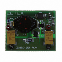
ZXSC100-EVAL Diodes Zetex, ZXSC100-EVAL Datasheet - Page 13

ZXSC100-EVAL
Manufacturer Part Number
ZXSC100-EVAL
Description
BOARD EVALUATION FOR ZXSC100
Manufacturer
Diodes Zetex
Datasheet
1.ZXSC100N8TA.pdf
(17 pages)
Specifications of ZXSC100-EVAL
Main Purpose
DC/DC, Step Up
Power - Output
330mW
Voltage - Output
3.3V
Current - Output
100mA
Voltage - Input
0.93 ~ 3.5 V
Regulator Topology
Boost
Board Type
Fully Populated
Utilized Ic / Part
ZXSC100
Lead Free Status / RoHS Status
Contains lead / RoHS non-compliant
ISSUE 3 - JANUARY 2004
Layout issues
Layout is critical for the circuit to function optimally in
terms of electrical efficiency, thermal considerations
and noise.
For ‘step-up converters’ there are four main current
loops, the input loop, power-switch loop, rectifier loop
and output loop. The supply charging the input
capacitor forms the input loop. The power-switch loop
is defined when Q1 is ‘on’, current flows from the input
through the inductor, Q1, R
Q1 is ‘off’, the energy stored in the inductor is
transferred to the output capacitor and load via D1,
forming the rectifier loop. The output loop is formed
by the output capacitor supplying the load when Q1 is
switched back off.
To optimise for best performance each of these loops
should be kept separate from each other and
interconnections made with short, thick traces thus
0.33W solution demo board layout
Top silk
Top Copper
SENSE
and to ground. When
13
Drill holes
Bottom Copper
minimising parasitic inductance, capacitance and
resistance. Also the sense resistor R2 should be
connected, with minimum trace length, between
emitter lead of Q1 and ground, again minimising stray
parasitics.
The layout for the 0.33W solution is shown below.
S E M I C O N D U C T O R S
Actual Size
ZXSC100


