DM163012 Microchip Technology, DM163012 Datasheet - Page 11
DM163012
Manufacturer Part Number
DM163012
Description
BOARD DEMO PICDEM FOR 16C781/782
Manufacturer
Microchip Technology
Datasheet
1.DM163012.pdf
(44 pages)
Specifications of DM163012
Supported Devices
PIC16C781/782
Interface Type
Serial
Processor To Be Evaluated
PIC16C781/782
For Use With
PIC16C781/782
Lead Free Status / RoHS Status
Contains lead / RoHS non-compliant
Lead Free Status / RoHS Status
Contains lead / RoHS non-compliant


1.5
1.6
2001 Microchip Technology Inc.
What the PICDEM™ MSC1 Is
Installing the GUI Software
The GUI software adheres to standard Windows
Perform the following procedure to install the GUI software:
1. Insert the CD containing the GUI software into your PC. Locate and dou-
2. Follow the instructions in the Installation Wizard. The installation creates
3. You can start the GUI software by using the Start
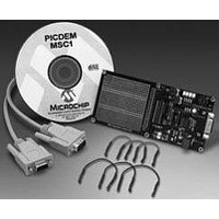
The Evaluation Tool is comprised of:
In stand-alone mode, the GUI is useful for discovering the features of all the
The GUI includes a Code Generator that can build the initialization assembly
The firmware of the PICDEM™ MSC1 allows you to:
easy to install for anyone familiar with other Windows applications.
PIC16C781/782 peripherals and identifying which registers are affected by
the different configurations. When used in conjunction with the evaluation
board, the GUI gives instant access to the PIC16C781/782 peripherals allow-
ing on-the-fly configuration changes by means of an RS-232 link between a
PC and the evaluation board.
code that corresponds to the selected configuration. Developers can use the
Code Generator to perform an entire configuration using the Evaluation Tool
and save it as a disk file.
ble-click on the setup.exe file in the CD Root Directory. An Installation
Wizard will guide you through the installation process.
an entry in the Start
PICDEM™ MSC1 icon for your desktop.
PICDEM™ MCS1 sequence.
• Printed circuit board
• PC based GUI
• UV erasable PIC16C782 with monitor firmware
• 9V power supply (IEC)
• RS-232C cable (9-pin)
• General purpose jumper wires
• Configure the inputs and outputs of each peripheral module using your
• Configure the operation of each peripheral module
• Load and view the contents of the Special Purpose Registers needed to
• Operate a dynamic conversion loop for scoping the Output of the DAC
• Save the configuration file that you have created and insert it into your
application parameters
run your application
Module
application software.
→
Overview and Installation
Programs group. The Wizard will also create a
®
conventions and should be
→
Programs
DS41178A-page 7
→
Related parts for DM163012
Image
Part Number
Description
Manufacturer
Datasheet
Request
R

Part Number:
Description:
Manufacturer:
Microchip Technology Inc.
Datasheet:
Part Number:
Description:
Manufacturer:
Microchip Technology Inc.
Datasheet:
Part Number:
Description:
Manufacturer:
Microchip Technology Inc.
Datasheet:
Part Number:
Description:
Manufacturer:
Microchip Technology Inc.
Datasheet:
Part Number:
Description:
Manufacturer:
Microchip Technology Inc.
Datasheet:
Part Number:
Description:
Manufacturer:
Microchip Technology Inc.
Datasheet:
Part Number:
Description:
Manufacturer:
Microchip Technology Inc.
Datasheet:
Part Number:
Description:
Manufacturer:
Microchip Technology Inc.
Datasheet: