DM300004-1 Microchip Technology, DM300004-1 Datasheet - Page 93
DM300004-1
Manufacturer Part Number
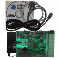
DM300004-1
Description
BOARD DEMO DSPICDEM.NET 1
Manufacturer
Microchip Technology
Series
dsPIC™r
Type
Microcontrollerr
Specifications of DM300004-1
Contents
*
Mcu Supported Families
DsPIC30F
Supported Devices
DsPIC30F6014
For Use With
PIC30F5013
Lead Free Status / RoHS Status
Lead free / RoHS Compliant
For Use With/related Products
FCC/JATE PSTN, Ethernet NIC
Lead Free Status / RoHS Status
na, Lead free / RoHS Compliant
Other names
DM300004-1R
DM300004-1R
DM300004-1R


2004 Microchip Technology Inc.
7.1.5
Two 5 kOhm potentiometers are connected to analog channels AN4 and AN5. The
voltage output range for each potentiometer is between 0 VDC and 5 VDC. The voltage
source is provided by VR1, through a low-pass filter. VR1 is the main voltage regulator
for all components on the development board.
7.1.6
Three switches, S1-S3, are connected to port pins RA12-RA14, respectively on the
dsPIC device. The signal lines are normally pulled up to +5 VDC through 10 k
resistors. Pressing the switch will short the line to ground. Port pins RA12-RA14 are
configured as the INT1-INT3 external interrupt pins.
7.1.7
Three red LEDs, LED1-LED3, are connected to port pins RC2 to RC4, respectively on
the dsPIC device. The LED anodes are tied to V
7.1.8
A dual channel digital potentiometer, MCP42050, is provided on the development
board. Control of the digital potentiometer is via the dsPIC SPI 1 communication
channel. The outputs of the digital potentiometer are applied to test points PW0 and
PW1.
7.1.9
A 2 x 16 character dot matrix LCD display is provided on the development board. The
dsPIC device accesses the LCD via PORTD pins RD0-RD7. The three LCD control
signals, RS, RW and E are connected to dsPIC port pins RA6, RB11 and RA7
respectively.
7.1.10
By way of the modular connector ICD, the MPLAB ICD 2 can be connected for low-cost
programming and debugging of the dsPIC device. Programming and debugging the
dsPIC device is through dedicated use of the PGC/EMUC/RB1 and PGD/EMUD/RB0
pins on the development board.
7.1.11
The dsPICDEM.net Development board is available in 2 configurations, one using the
Si3035 chipset for the FCC and JATE compliant designs and the other using Si3034
chipset for worldwide applications.The dsPIC communicates with this port with its Data
Converter Interface (DCI).
The Si3035 chipset is composed of the Si3012 DAA and a Si3021 AFE ICs. The dsPIC
communicates to the Si3021 AFE via its DCI peripheral module.The Si3034 chipset is
composed of a Si3014 DAA and the same Si3021 AFE.
A speaker is provided on the development board and provides for call progress
monitoring.
For detailed operation, please refer to the Si3034 and Si3035 data sheets available on
www.silabs.com.
Analog Potentiometers
Push Button Switches
LEDs
Digital Potentiometer
LCD Graphic Display
ICD Connector
Public-Switch Telephone Network (PSTN) Interface
dsPICDEM.net Development Hardware
DD
through a 1.2K resistor.
DS51471A-page 89
Ω
Related parts for DM300004-1
Image
Part Number
Description
Manufacturer
Datasheet
Request
R

Part Number:
Description:
Manufacturer:
Microchip Technology Inc.
Datasheet:
Part Number:
Description:
Manufacturer:
Microchip Technology Inc.
Datasheet:
Part Number:
Description:
Manufacturer:
Microchip Technology Inc.
Datasheet:
Part Number:
Description:
Manufacturer:
Microchip Technology Inc.
Datasheet:
Part Number:
Description:
Manufacturer:
Microchip Technology Inc.
Datasheet:
Part Number:
Description:
Manufacturer:
Microchip Technology Inc.
Datasheet:
Part Number:
Description:
Manufacturer:
Microchip Technology Inc.
Datasheet:
Part Number:
Description:
Manufacturer:
Microchip Technology Inc.
Datasheet: