B6TW-S08NF Omron, B6TW-S08NF Datasheet - Page 4
B6TW-S08NF
Manufacturer Part Number
B6TW-S08NF
Description
DEVELOPMENT KIT 8CH W/SOFTWARE
Manufacturer
Omron
Series
B6T Workbenchr
Type
Capacitive Sensorr
Specifications of B6TW-S08NF
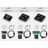
Contents
B6TS I/F Board, Serial Cable, CD-ROM, Sample Board and Flat Cable
Kit Contents
B6TS I/F Board, B6TY-S08LT (8-Ch) Demo Panel, Cables, Software And Docs
Svhc
No SVHC (15-Dec-2010)
Base Number
6
Development Tool Type
Evaluation Board
Kit Features
Evaluation Board
Lead Free Status / RoHS Status
Lead free / RoHS Compliant
For Use With/related Products
B6TS
Lead Free Status / Rohs Status
Supplier Unconfirmed
Other names
B6TWS08NF
Z2567
Z2567


Recommended operating conditions
Note: Unless otherwise specified, V
Electrical characteristics
Note: 1. Unless otherwise specified, V
Necessary timing conditions
Note: 1. Unless otherwise specified, V
4
V
V
V
I
I
V
V
I
I
I
—
—
—
t
t
t
t
t
T
t
t
t
T
T
T
OH
OL
IH
IL
CC
c(SCK)
w(SCKH)
w(SCKL)
d(SO)
h(SO)
h(SI)
w(BD)
w(CD)
w(CHG)
w(RESET)
OH
OL
su(SI)
su(SETUP)
dd
IH
IL
Designation
Designation
Designation
2. The period following receipt of the EEPROM write command in setup mode until the data write finishes.
2. This is the time period when the condition that CHG pulse width is at its minimum in the serial communication mode of normal measure-
3. The delay time for the mode shift between normal measurement mode and setup mode.
ment mode is set.
(CHG pin function is set to output at the end of every measurement [CHG bit = 0 with MODE command] and the sleep time is set to zero
[SLP command value = 0]).
Capacitive Touch Sensing ICs
Supply voltage
High input voltage
Low input voltage
High output voltage
Low output voltage
High output voltage
Low input voltage
High input voltage
Low input voltage
Supply voltage
Number of times of EEPROM write
EEPROM write time
EEPROM data retention period
Serial communication clock cycle time
Serial communication clock high pulse width
Serial communication clock low pulse width
Serial communication output delay time
Serial communication output hold time
Serial communication input setup time
Serial communication input hold time
Serial communication byte to byte interval
Serial communication command reception interval
CHG pulse width
Mode shift delay time
Reset pulse width
dd
= 4.5 – 5.5V, T
Item
dd
dd
= 4.5 – 5.5V, T
= 4.5 – 5.5V, T
Item
Item
OPR
B6TS
= -20 – 85° C.
OPR
OPR
= -20 – 85° C.
= -20 – 85° C.
I
I
V
V
Normal measurement mode
T
V
(Note 2)
T
OH
OL
OPR
OPR
I
I
dd
= 5V
= 0V
= 5mA
= -5mA
= 5V, T
= 0 – 60° C
= 55° C
Condition
OPR
(Note 2)
(Note 3)
Condition
= 25° C
Condition
Minimum
Minimum
V
0.8V
10000
dd
4.5
20
0
-2.0
dd
Rated value
Rated value
Minimum
Standard
Standard
8650
100
100
265
500
0.3
35
90
70
85
4
0
Rated value
Maximum
Maximum
Maximum
0.2V
150
5.5
V
V
2.0
80
-5
-5
5
5
dd
dd
dd
V
V
V
mA
mA
V
V
µA
µA
mA
Times
S
Years
nS
nS
nS
nS
nS
nS
nS
µS
µS
µS
µS
µS
Unit
Unit
Unit
Related parts for B6TW-S08NF
Image
Part Number
Description
Manufacturer
Datasheet
Request
R

Part Number:
Description:
DEVELOPMENT KIT 4CH W/SOFTWARE
Manufacturer:
Omron
Datasheet:

Part Number:
Description:
G6S-2GLow Signal Relay
Manufacturer:
Omron Corporation
Datasheet:
Part Number:
Description:
Compact, Low-cost, SSR Switching 5 to 20 A
Manufacturer:
Omron Corporation
Datasheet:
Part Number:
Description:
Manufacturer:
Omron Corporation
Datasheet:
Part Number:
Description:
Manufacturer:
Omron Corporation
Datasheet:
Part Number:
Description:
Manufacturer:
Omron Corporation
Datasheet:
Part Number:
Description:
Manufacturer:
Omron Corporation
Datasheet:
Part Number:
Description:
Manufacturer:
Omron Corporation
Datasheet:
Part Number:
Description:
Manufacturer:
Omron Corporation
Datasheet: