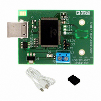
ADISEVAL/USBZ Analog Devices Inc, ADISEVAL/USBZ Datasheet
ADISEVAL/USBZ
Specifications of ADISEVAL/USBZ


Related parts for ADISEVAL/USBZ


ADISEVAL/USBZ Summary of contents
Page 1
... Note product is listed twice, it can be run at +3.3 or +5V. Connect the ADIS16xxx/PCBZ board, using connector J1, located on the bottom side of the ADISEVAL/USBZ. Refer to Figure 9 and Figure 10 and Figure 11 for diagrams of these connections not “keyed, ” so exercise caution in making this connection. Step #6 - Launch evaluation software Hook the USB Interface board to the cable and then launch the evaluation software by double clicking on the * ...
Page 2
... ADISEVAL/USBZ Figure 2. Installation Launch Screen (click on computer button) Figure 1. Installation Welcome Screen (Click OK) Rev. PrD | Page Preliminary Technical Data ...
Page 3
... Preliminary Technical Data Figure 3. Program Group Menu (Click Continue) Rev. PrD | Page ADISEVAL/USBZ ...
Page 4
... ADISEVAL/USBZ Figure 6. Giveio.exe Installation Confirmation Menu (Click Yes) Figure 4. Giveio.exe Installation Screen (Click Install) Figure 5. Giveio.exe License Agreement (Click I Agree) Rev. PrD | Page Preliminary Technical Data ...
Page 5
... Preliminary Technical Data Figure 8 .USB Driver Hardware Installation (Click on Continue Anyway) Figure 7. USB Driver Installation (Click Next) Rev. PrD | Page ADISEVAL/USBZ ...
Page 6
... ADISEVAL/USBZ Figure 9. USB Interface PCB connection with ADIS160xx/PCBZ, ADIS161xx/PCBZ, ADIS162xx/PCBZ, Top View Figure 10. USB Interface PCB connection with ADIS160xx/PCBZ, ADIS161xx/PCBZ, ADIS162xx/PCBZ, Bottom View Figure 11. USB Interface PCB connection with ADIS135x/PCBZ, Top View Preliminary Technical Data Rev. PrD | Page ...
Page 7
... Preliminary Technical Data Figure 12 – iSensor™ PC-USB Interface Board Layout (Top View) Figure 13 – iSensor™ PC-USB Interface Board Layout (Bottom View) Rev. PrD | Page ADISEVAL/USBZ ...
Page 8
... ADISEVAL/USBZ FIGURE FLAG NOTES: 1. Set the Device type to ADIS16003 or ADIS16006. Set the Interface to parallel and set the port address per ReadMeFirst.PDF 2. Set the axis being tested. Test function exercises a self-test during a single sweep on the screen. 3. Plot and log data to files. 4. Set up data logging parameters. ...
Page 9
... Set the output channel being tested. Test function exercises a self-test during a single sweep on the screen. 3. Plot and log data to files. 4. Set up data logging parameters. 5. Right click over Y-Axis to adjust scale and offset of the plot. 3 Figure 15. ADIS16080 and ADIS16100 Evaluation Software Rev. PrD | Page ADISEVAL/USBZ 4 ...
Page 10
... ADISEVAL/USBZ FIGURE FLAG NOTES: 1. Perform a single read of the ADIS16201’s output data 2. Start and stop continuous reading of the ADIS16201’s output data. Set the acquisition loop delay time. This provides rough control over sample times. Please note that this data will not have a high degree of coherence. ...
Page 11
... Graphical orientation. Note that for incline angle - 0°, the corner dot would be in the lower, left hand corner. 6. Alarm monitoring. Note that these turn red on alarm condition. They maintain their status until the Reset button is pressed, even if the error condition has cleared Figure 17. ADIS16203 Evaluation Software Rev. PrD | Page ADISEVAL/USBZ 4 ...
Page 12
... ADISEVAL/USBZ 6 1 FIGURE FLAG NOTES: 1. Perform a single read of the ADIS1625x’s output data 2. Start and stop continuous reading of the ADIS1625x’s output data. Set the acquisition loop delay time. This provides rough control over sample times. Please note that this data will not have a high degree of coherence. ...
Page 13
... Select individual sensor outputs for display. 3. Use Configuration menu to access sample rate, filtering, calibration, I/O control and all other internal configuration controls for the ADIS1635x products. 4. Use Device option to select which part to evaluate. Figure 19. ADIS1635x Evaluation Software Rev. PrD | Page ADISEVAL/USBZ EB07200-0-7/08(PrD) ...