DSP56309EVM Freescale Semiconductor, DSP56309EVM Datasheet - Page 2
DSP56309EVM
Manufacturer Part Number
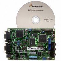
DSP56309EVM
Description
KIT EVALUATION FOR XC56309
Manufacturer
Freescale Semiconductor
Type
DSPr
Specifications of DSP56309EVM
Contents
Module Board, Installation Guide, Power Supply, Cable, Software and more
Description/function
Audio DSPs
Product
Audio Modules
For Use With/related Products
DSP56309
Lead Free Status / RoHS Status
Contains lead / RoHS non-compliant


DSP563xxEVM Overview
1
The DSP563xxEVM was designed to support all of the general purpose DSP563xx devices that are
currently available in the 196-pin MAP-BGA package: DSP56303, DSP56309, DSP56311 and
DSP56321. Included with the DSP563xxEVM is a sample case that contains all of these devices so the
user can choose which device to evaluate. The DSP563xxEVM contains a socket in which any of these
devices can be placed. Some of these devices have different core voltage requirements.
the jumper settings required to set the correct core voltage for each device.
The DSP563xxEVME User’s Manual (DSP563xxEVMEUM/D) describes the DSP563xxEVM in more
detail. This application note assumes that the DSP563xxEVM has been setup as described in Sections 1.2.1
- 1.2.3 of the User’s Manual. It is important for the timing of the Flash memory programming code to
verify that the DSP is driven with the 19.6608 MHz clock by setting the jumper at J13 (CLK_SEL) to pins
1 to 2. This application note does not use the Suite56 Software described in Section 1.2.4, so it is not
necessary to complete the steps in this section.
The DSP563xxEVM also includes:
This application note presents assembly code to program the Flash memory with user code to allow
stand-alone operations after setting the correct boot mode switches. This document also describes how to
write code to Flash memory that programs the DSP ESSI ports to communicate to the audio codec and
allow music to be passed from the audio input jack (J12) to the DSP and back to the audio output jack (J10)
or the headphone jack (J15). Please see Appendix A of the DSP563xxEVME User’s Manual for a full
description of the audio codec programming code.
2
•
•
•
•
•
•
•
DSP563xxEVM Overview
64K × 24-bit fast static RAM (FSRAM) for expansion memory
256K × bit-bit Flash memory for stand-alone operation
16-bit CD-quality audio codec
headers to facilitate direct access for off board devices to the on-chip peripheral ports
14-pin JTAG/OnCE connector that allows direct connection of an external command converter
buttons for asserting RESET and the IRQ pins of the DSP
switches for setting the DSP boot mode.
DSP56303
DSP56309
DSP56311
DSP56321
Device
3.3 V
3.3 V
1.8 V
1.6 V
Using Symphony™ Studio with the DSP563xxEVM, Rev. 0
Voltage
Table 1-1. DSP563xxEVM Voltage Jumper Settings
Core
1 to 2 (3.3 V)
1 to 2 (3.3 V)
2 to 3 (Low voltage determined by J16)
2 to 3 (Low voltage determined by J16)
J18 (Voltage Select) Setting
—
—
3 to 4
5 to 6
J16 (Low Voltage
Select) Setting
Freescale Semiconductor
Table 1-1
shows
Related parts for DSP56309EVM
Image
Part Number
Description
Manufacturer
Datasheet
Request
R

Part Number:
Description:
Manufacturer:
Freescale Semiconductor, Inc
Datasheet:
Part Number:
Description:
Manufacturer:
Freescale Semiconductor, Inc
Datasheet:
Part Number:
Description:
Manufacturer:
Freescale Semiconductor, Inc
Datasheet:
Part Number:
Description:
Manufacturer:
Freescale Semiconductor, Inc
Datasheet:
Part Number:
Description:
Manufacturer:
Freescale Semiconductor, Inc
Datasheet:
Part Number:
Description:
Manufacturer:
Freescale Semiconductor, Inc
Datasheet:
Part Number:
Description:
Manufacturer:
Freescale Semiconductor, Inc
Datasheet:
Part Number:
Description:
Manufacturer:
Freescale Semiconductor, Inc
Datasheet:
Part Number:
Description:
Manufacturer:
Freescale Semiconductor, Inc
Datasheet:
Part Number:
Description:
Manufacturer:
Freescale Semiconductor, Inc
Datasheet:
Part Number:
Description:
Manufacturer:
Freescale Semiconductor, Inc
Datasheet:
Part Number:
Description:
Manufacturer:
Freescale Semiconductor, Inc
Datasheet:
Part Number:
Description:
Manufacturer:
Freescale Semiconductor, Inc
Datasheet:
Part Number:
Description:
Manufacturer:
Freescale Semiconductor, Inc
Datasheet:
Part Number:
Description:
Manufacturer:
Freescale Semiconductor, Inc
Datasheet: