6421 Crydom Co., 6421 Datasheet
6421
Manufacturer Part Number
6421
Description
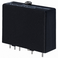
I/O MODULE2.4-6V SIP DC INPUT
Manufacturer
Crydom Co.
Series
6r
Type
ACr
Datasheet
1.6421.pdf
(2 pages)
Specifications of 6421
Color
Black
Style
Standard
Voltage - Input
5VDC (3.5 ~ 6VDC)
Current - Input
20mA
Voltage - Output
12 ~ 140VAC (120VAC Nom)
Current - Output
0.02 ~ 3.5A
Turn On Time
1/2 Cycle
Turn Off Time
1/2 Cycle
Features
Hold Down Screw
Leaded Process Compatible
No
No. Of Analog Outputs
1
No. Of Digital Inputs
1
Output Voltage Min
12V
Supply Voltage Min
2.4VDC
Output Current Max
3.5A
Signal Input Type
3.5 To 6VDC
Output Type
AC
Input Type
DC
Input Voltage (max)
5V
Output Voltage (max)
140V
Input Current (max)
20mA
Output Current
3.5A
Isolation Voltage
4kV
Output Device
Triac
Pin Count
5
Mounting
Through Hole
Operating Temp Range
-40C to 80C
Operating Temperature Classification
Commercial
Rad Hardened
No
Lead Free Status / RoHS Status
Lead free / RoHS Compliant
Lead Free Status / RoHS Status
Lead free / RoHS Compliant, Lead free / RoHS Compliant
Other names
CC1243
Available stocks
Company
Part Number
Manufacturer
Quantity
Price

Company:
Part Number:
642179
Manufacturer:
MOLEX
Quantity:
35 000
Company:
Part Number:
64219710
Manufacturer:
DELPHI
Quantity:
40 000


INPUT SPECIFICATIONS
(All voltages referenced to pin 5)
Nominal Input Voltage [Vdc]
Output Module Type
Must Turn On Voltage Range @ pin 4 [Vdc]
Must Turn Off Voltage Range @ pin 4 [Vdc]
Max. Input On-Current (Sink) @ pin 4 [µA]
Max. Input On-Current (Source) @ pin 4 [µA]
Max. Output Off-State Input Current @ pin 4 [µA]
Logic Supply Voltage Range [Vdc]
Max. Logic Supply Current @ 5Vdc (w/o LED) [mA]
Max. Logic Supply Current @ 5Vdc (w/ LED) [mA]
Nominal Input Voltage [Vdc]
Output Module Type
Must Turn On Voltage Range @ pin 4 [Vdc]
Must Turn Off Voltage Range @ pin 4 [Vdc]
Max. Input On-Current (Sink) @ pin 4 [µA]
Max. Input On-Current (Source) @ pin 4 [µA]
Max. Input Current for Output Off-State @ pin 4 [µA]
Logic Supply Voltage Range [Vdc]
Max. Logic Supply Current @ 5Vdc (w/o LED) [mA]
Max. Logic Supply Current @ 5Vdc (w/ LED) [mA]
OUTPUT SPECIFICATIONS
Load Current Range @ 45˚ C [A]
Load Voltage Range [Vdc]
Max. Surge Current 1 Cycle (Non-Rep) [Apk]
Max. On-State Voltage [Vdc]
Max. Off-State Leakage [mA]
Max. Turn On Time
Max. Turn Off Time
Transient Overvoltage [Vpk]
GENERAL NOTES
FastFax Document No. 308
081398, PAGE 1 OF 2
status indication.
maintain output off-state.
LED optional. Placed in series with pin 3 for
Max. allowable leakage current from driver
AC Output Buffered Modules
• Compatible with 5 & 15
• Buffered Inverting and
• Zero Voltage AC Switching
For recommended applications and more information contact:
USA: (800) 8 CRYDOM • (800) 827-9366 • (619) 715-7200 • fax (619) 715-7280
Crydom Corp, 9525 Chesapeake Drive, San Diego, CA 92123 • e-mail: sales@crydom.com
WEB SITE: http://www.crydom.com FASTFAX Product Information: (888) 267-9191
UK: (44)1202 812300 • fax (44)1202 812340 Crydom International Ltd., 85, Condor Close,
Woolsbridge Industrial Estate, Three-Legged Cross. Wimborne, Dorset, England BH21 6SU
GERMANY: (49) (0)6874 182580 • fax (49)(0)6874 182585 Crydom GmbH,
Gewerbegebiet Im Schachen, D-66687 Nunkirchen, Germany • e-mail: vertrieb@crydom.com
Volt Logic Systems
Non-Inverting Modules
Non-Inverting
Non-Inverting
100 @ 0.0V
250 @ 0.0V
175 @ 2.0V
0.02 - 3.5
1/2 Cycle
1/2 Cycle
75 @ 0.8V
12 - 140
2.4 - 6.0
0.0 - 0.8
3.5 - 6.0
0.0 - 2.0
8.0 - 18
10 - 18
6411
6441
400
1.5
5.0
10
15
10
80
—
—
20
15
25
22
—
—
5
250 @ 6.0V
200 @ 18V
75 @ 2.4V
75 @ 8.0V
Inverting
Inverting
0.02 - 3.5
1/2 Cycle
1/2 Cycle
12 - 140
2.4 - 6.0
0.0 - 0.8
3.5 - 6.0
©1998 CRYDOM CORP Specifications subject to change without notice.
8.0 - 18
0.0 - 2.0
10 - 18
6421
6451
400
1.5
5.0
10
20
15
15
10
25
22
80
—
—
—
—
5
Buffered output modules contain addi-
tional internal amplification to reduce
drive requirements to a level suitable for
the MOS devices used in many micro-
processor systems. To further reduce
the need for additional interface com-
ponents, they are available with both
inverting and non-inverting inputs, for
5 volt or 15 volt logic.
Non-Inverting
Non-Inverting
100 @ 0.0V
175 @ 2.0V
250 @ 0.0V
75 @ 0.8V
0.02 - 3.5
1/2 Cycle
1/2 Cycle
2.4 - 6.0
3.5 - 6.0
24 - 280
0.0 - 0.8
0.0 - 2.0
8.0 - 18
6412
6442
10 -18
600
1.5
5.0
20
15
15
25
22
80
—
—
—
—
10
10
5
250 @ 6.0V
200 @ 18V
75 @ 2.4V
75 @ 8.0V
Inverting
Inverting
0.02 - 3.5
1/2 Cycle
1/2 Cycle
2.4 - 6.0
0.0 - 0.8
3.5 - 6.0
24 - 280
8.0 - 18
0.0 - 2.0
6422
6452
10 -18
600
1.5
5.0
10
20
15
15
10
25
22
80
—
—
—
—
5
9002
Related parts for 6421
Image
Part Number
Description
Manufacturer
Datasheet
Request
R

Part Number:
Description:
RELAY SSR 10-35MA INPUT 16 DIP
Manufacturer:
Crydom Co.
Datasheet:
Part Number:
Description:
RELAY SSR 3.5-10VDC INPUT 16 DIP
Manufacturer:
Crydom Co.
Datasheet:

Part Number:
Description:
RELAY SSR 5A 480VAC SIP
Manufacturer:
Crydom Co.
Datasheet:

Part Number:
Description:
RELAY SSR 12A 240VAC DC
Manufacturer:
Crydom Co.
Datasheet:

Part Number:
Description:
RELAY SSR 25A 240VAC DC
Manufacturer:
Crydom Co.
Datasheet:

Part Number:
Description:
POWER CONTROL SSR 15A DC IN
Manufacturer:
Crydom Co.
Datasheet:
Part Number:
Description:
RELAY SSR 125A 480VAC DC INPUT
Manufacturer:
Crydom Co.
Datasheet:
Part Number:
Description:
RELAY SSR 5A 380VAC AC OUT SIP
Manufacturer:
Crydom Co.
Datasheet:
Part Number:
Description:
RELAY SSR 10A 240VAC DC
Manufacturer:
Crydom Co.
Datasheet:
Part Number:
Description:
RELAY SSR 25A 120VAC AC
Manufacturer:
Crydom Co.
Datasheet:
Part Number:
Description:
RELAY SSR 10-35MA INPUT 16 DIP
Manufacturer:
Crydom Co.
Datasheet:
Part Number:
Description:
RELAY SSR 3.5-10VDC INPUT 16 DIP
Manufacturer:
Crydom Co.
Datasheet:
Part Number:
Description:
RELAY SSR AC 2A 120VAC PNL MNT
Manufacturer:
Crydom Co.
Datasheet:

Part Number:
Description:
RELAY SSR AC OUT 1CH 0.3A PCB
Manufacturer:
Crydom Co.
Datasheet:

Part Number:
Description:
RELAY SSR 3A PC MNT W/SNUBER
Manufacturer:
Crydom Co.
Datasheet:
6421 Summary of contents
Page 1
... FastFax Document No. 308 081398, PAGE Output Buffered Modules • Compatible with 5 & 15 Volt Logic Systems • Buffered Inverting and Non-Inverting Modules • Zero Voltage AC Switching 6411 6421 5 5 Non-Inverting Inverting 0.0 - 0.8 2.4 - 6.0 2.4 - 6.0 0 0.8V — ...
Page 2
3.5 3.0 2.5 2.0 1.5 1 AMBIENT TEMPERATURE (ºC) Max. Load Current vs. Temp. BUFFERED OUTPUT MODULES A ...