6311 Crydom Co., 6311 Datasheet - Page 2

6311
Manufacturer Part Number
6311
Description
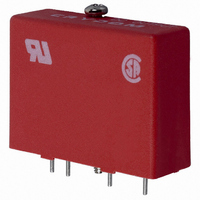
I/O MODULE 0-.8V SIP DC INPUT
Manufacturer
Crydom Co.
Series
6r
Type
DCr
Datasheet
1.6311.pdf
(2 pages)
Specifications of 6311
Color
Red
Style
Standard
Voltage - Input
5VDC (3.5 ~ 6VDC)
Current - Input
20mA
Voltage - Output
3 ~ 60VDC
Current - Output
0.02 ~ 3.5A
Turn On Time
0.10ms
Turn Off Time
0.10ms
Features
Hold Down Screw
Leaded Process Compatible
No
No. Of Analog Outputs
1
Output Voltage Min
3V
Supply Voltage Min
0VDC
Output Current Max
3.5A
Signal Input Type
3.5 To 6VDC
Output Type
DC
Output Voltage
60V
Output Current
3.5A
No. Of Analog Inputs
1
No. Of Outputs
1
Output Current Min
0.02A
Rohs Compliant
Yes
Lead Free Status / RoHS Status
Lead free / RoHS Compliant
Lead Free Status / RoHS Status
Lead free / RoHS Compliant, Lead free / RoHS Compliant
Other names
6311
CC1239
CC1239
Available stocks
Company
Part Number
Manufacturer
Quantity
Price
Company:
Part Number:
631165-2
Manufacturer:
TE
Quantity:
52 925
Company:
Part Number:
631165-2
Manufacturer:
TE
Quantity:
35 000
Company:
Part Number:
63119-1
Manufacturer:
TE/AMP
Quantity:
30 000
Company:
Part Number:
63119-1
Manufacturer:
TE
Quantity:
20 000
Company:
Part Number:
63119-1
Manufacturer:
tyco
Quantity:
35 000
BUFFERED OUTPUT M ODULES
A buffered non-inverting module turns on when pin 4 is held in the
low state (logic 0), the same as standard modules driven in the sink
mode. A buffered inverting module conversely turns on when pin 4
is held high (logic 1). In the absence of an input signal and/or logic
supply (open Circuit), all models will be in the off-state.
Buffered modules may be used with standard 5 pin PB or MS
mounting boards. However, the 3.3K pull-up resistor will add to the
logic drive current of a non-inverting module and may be removed.
For an inverting module, the resistor must be removed to avoid a
false ÒonÓ command, unless a Ònor mally closedÓ condition is desir -
able for use with a ground seeking (logic 0) signal source.
FastFax Document No. 309
Rev. 031902
PAGE 2 OF 2
C U R R E N T D E R AT I N G C U RV E
3.0
2.5
2.0
1.5
1.0
3.5
0
Max. Load Current vs. Temp.
AMBIENT TEMPERATURE (˚C)
20
40
60
DC O utput B uffered M odules
80
GENERAL SPECIFICATIONS
Min. Dielectric Input/Output (1 minute)
Min. Isolation Resistance Input/Output (@ 500V)
Capacitance input to output
Temperature Range Ñ Operating
Temperature Range Ñ Storage
For recommended applications and more information contact:
USA: Sales Support (877) 502-5500 Tech Support (877) 702-7700 FAX (619) 710-8540
Crydom Corp, 2320 Paseo de las Americas, Ste. 201, San Diego, CA 92154
Email: sales@crydom.com WEB SITE: http://www.crydom.com
UK: +44 (0)1202 365070 • FAX +44 (0)1202 365090 Crydom International Ltd., 7 Cobham
Road, Ferndown Industrial Estate, Ferndown, Dorset BH21 7PE, Email: intsales@crydom.com.
GERMANY: +49 (0)180 3000 506
DC LOGIC
SUPPLY
DC LOGIC INPUT
COM (-)
#4-40. PHILLIPS
DOWN SCREW
.040 (1.0) DIA.
© 2002 CRYDOM CORP Specifications subject to change without notice.
(+)
HEAD HOLD
(5 PLACES)
W I R I N G & M E C H A N I C A L D I A G R A M S
CAPTIVE
3
4
5
(31.7)
All dimensions are in inches (millimeters)
(6.3)
1.25
.25
INV or
Non-INV
Logic
5
4
3
BOTTOM VIEW
(40.6)
1.60
(35.5)
1.40
(43.1)
1.70
2
Drive
Circuit
(30.5)
1.20
(25.4)
1.00
(17.8)
1
.70
(7.6)
.30
-40û C to 125˚C
-40û C to 80˚C
.100
(2.5)
4,000 VRMS
(7.6)
10
.30
1
2
DC
Output
10
8 pF
(15.2)
.60
Ohms
LOAD
(+)
(-)


