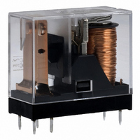
G2R-1A-E-DC12 Omron, G2R-1A-E-DC12 Datasheet - Page 16

G2R-1A-E-DC12
Manufacturer Part Number
G2R-1A-E-DC12
Description
RELAY PWR SPST-NO 16A 12VDC
Manufacturer
Omron
Series
G2Rr
Datasheets
1.G2R-1A-E-DC12.pdf
(14 pages)
2.G2R-1A-E-DC12.pdf
(30 pages)
3.G2R-2-SND_DC24S.pdf
(19 pages)
Specifications of G2R-1A-E-DC12
Relay Type
General Purpose
Coil Resistance
275 Ohms
Contact Form
SPST-NO (1 Form A)
Contact Rating (current)
16A
Switching Voltage
380VAC, 125VDC - Max
Coil Type
Standard
Coil Current
43.6mA
Coil Voltage
12VDC
Turn On Voltage (max)
8.4 VDC
Turn Off Voltage (min)
1.8 VDC
Mounting Type
Through Hole
Termination Style
PC Pin
Circuit
SPST-NO (1 Form A)
Contact Rating @ Voltage
16A @ 250VAC
Control On Voltage (max)
8.4 VDC
Control Off Voltage (min)
1.8 VDC
Contact Rating
16 A
Contact Termination
Solder Pin
Mounting Style
Through Hole
Power Consumption
530 mW
Contact Material
Silver Alloy
Coil Voltage Vdc Nom
12V
Contact Current Max
16A
Contact Voltage Ac Nom
250V
Contact Voltage Dc Nom
30V
Contact Configuration
SPST-NO
Lead Free Status / RoHS Status
Lead free / RoHS Compliant
Lead Free Status / RoHS Status
Lead free / RoHS Compliant, Lead free / RoHS Compliant
Other names
G2R-1A-E-DC12
G2R1AEDC12
Z2307
G2R1AEDC12
Z2307
Available stocks
Company
Part Number
Manufacturer
Quantity
Price
Company:
Part Number:
G2R-1A-E-DC12V
Manufacturer:
OMRON
Quantity:
12 000
Company:
Part Number:
G2R-1A-E-DC12V
Manufacturer:
OMRON
Quantity:
12 000
PCB Design
■ Soldering
As demands for more compact electronic devices have grown, so
have demands declined for the plug-in relays that requires a bulky
socket for connection. This trend has lead to the development of
relays that can be soldered directly onto the PCB. Smaller relays
have made possible great density increases on the PCB, which in
turn reduces the size of the product or device. However, unless the
relay is fully sealed, when soldered onto a PCB, flux may penetrate
into the housing, adversely affecting the internal circuitry.
The following points will help when designing a product which uses
relays. This section points out details to be noted when soldering a
relay to a PCB.
■ PCB Materials
Generally, the substrate of a PCB is made of glass epoxy (GE),
paper epoxy (PE), or paper phenol (PP). Of these, the glass-epoxy or
paper-epoxy PCB is recommended for mounting relays. See the fol-
lowing table
■ PCB Thickness
PCBs having a thickness of 0.8, 1.2, 1.6, or 2.0 mm are generally
used. A PCB that is 1.6 mm thick is best for mounting a PCB relay,
considering the weight of the relay and the length of the terminals.
(The terminal length of OMRON relays is 3, 3.5, or 4.0 to 5.0 mm.)
■ Terminal Hole Diameter and
Select the appropriate terminal hole and land diameters from the fol-
lowing table, based on the PCB mounting hole drawing. Land diame-
ters may be reduced to less than those listed below if the through-
hole connection process is to be employed.
16
Electrical characteristics
Mechanical characteristics
Cost Effectiveness
0.6 mm
0.8 mm
1.0 mm
1.2 mm
1.3 mm
1.5 mm
1.6 mm
2.0 mm
Land Diameter
Normal
Terminal Hole Diameter
Item
Electromechanical Relays
Terminal Hole and Land Diameters
3.5
±0.1 mm
Tolerance
resistance hardly affected by humidity.
change in temperature or humidity.
Suitable for through-hole PCBs and
multi-layered PCBs.
Expensive
High insulation resistance. Insulation
Little expansions/shrinkage caused by
Glass Epoxy (GE)
1.5 mm
1.8mm
2.0mm
2.5mm
2.5mm
3.0mm
3.0mm
3.0mm
Minimum Land
Technical Information
Diameter
Epoxy Based
Fair
Fair
Fair
■ PCB Selection
In general, relays are directly mounted and soldered onto a PCB.
Although seemingly an uninvolved process, soldering and its related
processes of flux application, relay mounting, heat application, and
washing can be detrimental to a relay’s performance. For example, if
the PCB were to warp, the internal mechanism of the relay could
become distorted, degrading the performance characteristics. Thus it
could be said that the relay’s characteristics are also affected by the
size, thickness, and material of the PCB. Therefore, carefully select a
PCB that will not jeopardize the performance of the relay.
■ Shape of Lands
The land section should be on the center line of the copper-foil pat-
tern, so that the soldered fillets become uniform.
A break in the circular land area will prevent molten solder from filling
holes reserved for components which must be soldered manually
after the automatic soldering of the PCB is complete.
Correct
Incorrect
Paper Epoxy (PE)
Insulation resistance degraded by hu-
midity.
Much expansion/shrinkage caused by
changes in temperature or humidity.
Not suitable for through-hole PCB.
Fair
0.2 to 0.5 mm
Break in land
Paper Phenol (PP)
Phenol-based


