SPECIFICATIONS
Contact
Coil
#1 This value can change due to the switching frequency, environmental conditions,
Type
Arrangement
Contact material
Initial contact resistance
(By voltage drop 6 V DC 1 A)
Contact voltage drop
Rating
(resistive
load)
Expected
life
Nominal operating power
and desired reliability level, therefore it is recommended to check this with the
actual load.
.787
20
Nominal
switching
capacity
Max. carrying
current
Min. switching
capacity
Mechanical
(at 120 cpm)
Electrical
(at rated load)
15
.591
22
.866
#1
.787
20
N.O.: 35 A 14 V DC
N.C.: 20 A 14 V DC
(at 35 A 14 V DC)
(at 20 A 14 V DC)
Max. N.O.: 0.5 V
12 V coil voltage
Max. N.C.: 0.3 V
(Internal resistor
at 85°C 185°F)
at 85°C 185°F)
1 A 12 V DC
N.O.: 20 A
N.C.: 10 A
(14 V DC,
(14 V DC,
Flux-resistant type: Min. 10
mm
1.5 W
1.7 W
type)
Sealed type: Min. 5 × 10
15
.591
1 Form A, 1 Form C
inch
23
.906
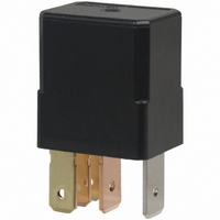
AUTOMOTIVE MICRO-ISO
Max. 15mΩ
Silver alloy
Min. 10
FEATURES
• Small size:
20 mm(L)×15 mm(W)×22 mm(H)
.787 inch(L)×.591 inch(L)×.866 inch(H)
• Wide line-up
PC board and Plug-in type, Resistor and
diode inside type.
24V DC type is also available.
• Compact and high-capacity 35A load
switching
N.O.: 35A 14V DC, N.C.: 20A 14V DC
(Sealed type)
Min. 5 × 10
N.O.: 35A 14V DC, N.C.: 20A 14V DC
(Flux-resistant type)
Min. 10
• Micro-ISO type terminals
N.O.: 15 A 28 V DC
N.C.: 8 A 28 V DC
(at 15 A 28 V DC)
24 V coil voltage
Max. N.O.: 0.3 V
Max. N.C.: 0.2 V
(at 8 A 28 V DC)
(Internal resistor
at 85°C 185°F)
at 85°C 185°F)
6
1 A 24 V DC
N.O.: 15 A
(28 V DC,
(28 V DC,
N.C.: 8 A
1.8 W
2.0 W
type)
5
RELAY
*12V DC type
4
4
5
*
1
Characteristics
Remarks
*
*
*
*
*
*
*
*
*
Type
Max. operating speed
(at nominal switching capacity)
Initial insulation resistance*
Initial breakdown
voltage*
Operate time*
(at nominal voltage) (at 20°C 85°F)
Release time*
(at nominal voltage) (at 20°C 85°F)
Shock resistance
Vibration
resistance
Conditions for
operation, trans-
port and storage*
(Not freezing and
condensing at low
temperature)
Mass
1
2
3
4
5
6
7
8
9
At nominal switching capacity, operating frequency: 2s ON, 2s OFF
Measurement at same location as “Initial breakdown voltage” section.
Detection current: 10mA
Excluding contact bounce time.
Half-wave pulse of sine wave: 11 ms; detection time: 10 µs
Half-wave pulse of sine wave: 6 ms
Time of vibration for each direction; X, Y, Z direction: 4 hours
Refer to 6. Conditions for operation, transport and storage mentioned in
AMBIENT ENVIRONMENT
Ambient temperature 125°C
Please contact us for details.
3
X
4
4
Y
Z
8
CM RELAYS
Between open
contacts
Between contacts
and coil
Functional*
Destructive*
Functional
Destructive*
Ambient temp.*
Humidity
TYPICAL APPLICATIONS
• Fan motor
• Heater
• Head lump
• Air Compressor
• EPS
• ABS
• Blower fan
• Defogger, etc.
257°F
2
5
type is also considerable on request.
6
7
9
24V coil type
Min. 20 MΩ (at 500 V DC)
Max. 15 ms (with diode)
Min. 1,000m/s
Min. 44.1 m/s
Min. 44.1 m/s
5% R.H. to 85% R.H.
Min. 200 m/s
500 Vrms for 1 min.
500 Vrms for 1 min.
10 Hz to 2,000 Hz,
Approx. 20g
–40°F to + 185°F
10 Hz to 500 Hz,
–40°C to + 85°C
Max. 10 ms
Max. 10 ms
15 cpm
12V coil type
2
2
2
2
.71oz
{4.5 G}
{4.5 G}
{20G}
{100G}
CM