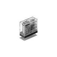
G2R-1-E-ASI-DC12 Omron, G2R-1-E-ASI-DC12 Datasheet - Page 3

G2R-1-E-ASI-DC12
Manufacturer Part Number
G2R-1-E-ASI-DC12
Description
RELAY PWR SPDT 16A 12VDC PCB
Manufacturer
Omron
Series
G2Rr
Specifications of G2R-1-E-ASI-DC12
Relay Type
General Purpose
Contact Form
SPDT (1 Form C)
Contact Rating (current)
16A
Switching Voltage
380VAC, 125VDC - Max
Coil Type
Standard
Coil Current
43.6mA
Coil Voltage
12VDC
Turn On Voltage (max)
8.4 VDC
Turn Off Voltage (min)
1.8 VDC
Mounting Type
Through Hole
Termination Style
PC Pin
Circuit
SPDT (1 Form C)
Contact Rating @ Voltage
16A @ 250VAC
Control On Voltage (max)
8.4 VDC
Control Off Voltage (min)
1.8 VDC
Contact Rating
16 A
Contact Termination
Solder Pin
Mounting Style
Through Hole
Power Consumption
530 mW
Contact Material
Silver Tin Indium Alloy
Coil Resistance
275 Ohms
Lead Free Status / RoHS Status
Lead free / RoHS Compliant
Other names
G2R1EASIDC12
Operation
■ Single-side Stable Relays
The contacts of this simple type of relay momentarily turn ON and
OFF, depending on the energized state of the coil.
■ Dual Coil, Latching Relays
This latching relay has two coils: set and reset. It can retain the ON
or OFF states even when a pulsating voltage is supplied, or when the
voltage is removed.
Contact Styles
Contact ratings are generally indicated according to resistive loads
and inductive loads (cosφ = 0.4 or L/R = 7 ms). Contact shape and
material are also shown to guide the customer in selection of a
model suitable for the intended load and required service life.
(Standard/Non-latching)
Mounting orientation mark
Mounting orientation mark
Terminal Arrangement/
Internal Connections
(Bottom View)
Terminal Arrangement/
Internal Connections
(Bottom View)
S: Set coil
R: Reset coil
Example
S R
0.001
0.01
0.1
1
Gold-clad
bifurcated
crossbar
contact
Electromechanical Relays
Gold-plated
single contact
■ Single Coil, Latching Relays
Unlike the dual coil latching relay, the single-winding latching relay
has only one coil. This coil, however, serves as both the set and reset
coils, depending on the polarity (direction) of current flow. When cur-
rent flows through the coil in the forward direction, it functions as a
set coil; when current flows through the coil in the reverse direction, it
functions as a reset coil.
■ Built-in Diode
A diode is built into some relays, wired in parallel with the coil to
absorb the counterelectromotive force (counter emf) generated by
the coil.
■ Built-in Operation Indicator
Some relays are provided with a light-emitting diode (LED), wired in
parallel with the coil. This permits a fast-check of the relay’s operat-
ing status.
When used at extremely low loads, the failure rate differs according
to the contact material and contact method, as shown in the figure.
For example, in comparing a single contact point with a bifurcated
contact point, the bifurcated contact model has higher parallel redun-
dancy and will therefore exhibit a lower failure rate.
Gold-plated
bifurcated
contact
10 VDC (constant)
Mounting orientation mark
Technical Information
Load current (mA)
Terminal Arrangement/
Internal Connections
(Bottom View)
S: Set coil
R: Reset coil
S R
3


