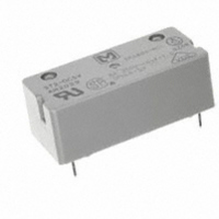
ST2-DC5V Panasonic Electric Works, ST2-DC5V Datasheet - Page 2

ST2-DC5V
Manufacturer Part Number
ST2-DC5V
Description
RELAY PWR DPST-NO 8A 5V PC MNT
Manufacturer
Panasonic Electric Works
Series
STr
Specifications of ST2-DC5V
Relay Type
General Purpose
Contact Form
DPST (2 Form A)
Contact Rating (current)
8A
Switching Voltage
380VAC
Coil Type
Standard
Coil Current
47.6mA
Coil Voltage
5VDC
Turn On Voltage (max)
4 VDC
Turn Off Voltage (min)
0.5 VDC
Mounting Type
Through Hole
Termination Style
PC Pin
Circuit
DPST (2 Form A)
Contact Rating @ Voltage
8A @ 380VAC
Control On Voltage (max)
4 VDC
Control Off Voltage (min)
0.5 VDC
Brand/series
ST Series
Current, Rating
8 A
Diameter, Mounting
0.055 in. Dia. (Hole)
Dimensions
1.220 in. L x 0.551 in. W x 0.445 in. H
Function
General Purpose
Latch Type
Single Side Stable
Material, Contact
Gold Flash Over Silver Alloy
Number Of Pins
6
Standards
UL, CSA, VDE
Termination
Solder
Voltage, Control
5 VDC
Voltage, Rating
380 VAC
Lead Free Status / RoHS Status
Lead free / RoHS Compliant
Other names
255-1291
Available stocks
Company
Part Number
Manufacturer
Quantity
Price
Part Number:
ST2-DC5V
Manufacturer:
NAIS
Quantity:
20 000
Company:
Part Number:
ST2-DC5V-F
Manufacturer:
NAIS/PANASONIC
Quantity:
20 000
Part Number:
ST2-DC5V-Z1
Manufacturer:
PANASONIC/松下
Quantity:
20 000
TYPES AND COIL DATA (at 20 ° C
Single side stable
2 coil latching
DIMENSIONS
REFERENCE DATA
1. Max. switching power
ST1-DC3V
ST1-DC5V
ST1-DC6V
ST1-DC9V
ST1-DC12V
ST1-DC24V
ST1-DC48V
ST1-L2-DC3V
ST1-L2-DC5V
ST1-L2-DC6V
ST1-L2-DC9V
ST1-L2-DC12V ST2-L2-DC12V
ST1-L2-DC24V ST2-L2-DC24V
ST1-L2-DC48V ST2-L2-DC48V
1 Form A
1 Form B
1 Form A
1 Form B
8
0.5
0.2
0.1
10
7.62
.300
5
2
1
1
2
DC resistive load
Part No.
Part No.
7 6
10
10.16
1.220
.400
31.0
ST2-DC3V
ST2-DC5V
ST2-DC6V
ST2-DC9V
ST2-DC12V
ST2-DC24V
ST2-DC48V
ST2-L2-DC3V
ST2-L2-DC5V
ST2-L2-DC6V
ST2-L2-DC9V
20
3
2 Form A
2 Form A
7.62
.300
inductive load
AC
4
(cosϕ =0.4)
50
5
Voltage, V
General tolerance: ±0.2
3.5
100 200 300
AC resistive load
11.0
.433
.138
.012
0.3
Nominal
Nominal
voltage,
voltage,
V DC
V DC
12
24
48
12
24
48
3
5
6
9
3
5
6
9
10.16
.400
.551
14
±.008
2. Life curve
Pick-up voltage,
1,000
Set and reset
V DC (max.)
V DC (max.)
500
200
100
50
20
10
voltage,
19.2
38.4
19.2
38.4
68 °
2.4
4.0
4.8
7.2
9.6
2.4
4.0
4.8
7.2
9.6
1
2
F)
(Copper-side view)
AC 250 V, 125 V inductive load
PC board pattern
3
AC 250 V, 125 V resistive load
8-DIA. 1.4
4
Current, A
.055
5
V DC (min.)
Tolerance: ±0.1
Drop-out
voltage,
Maximum allowable voltage,
6
0.3
0.5
0.6
0.9
1.2
2.4
4.8
7
V DC (60 ° C 140°F)
2 coil latching
types only.
8
2.54
.100
(Pf = 0.4)
9 10
13.5
18.0
36.0
72.0
2.54
.100
4.5
7.5
9.0
±.004
V DC (60 ° C 140°F)
allowable voltage,
Maximum
13.5
18.0
36.0
72.0
4.5
7.5
9.0
Diagram shows the “reset”
position when terminals 3 and
4 are energized. Energize
terminals 1 and 2 to transfer
contacts.
3. Coil temperature rise
Sample: ST1-DC24V
1
8
1
8
– +
–
1a1b
1a1b
60
50
40
30
20
10
7
2
7
0
Schematic (Bottom view)
(Deenergized condition)
Coil resistance,
Coil resistance,
6
3
6
Single side stable
+ –
(Reset condition)
0.1
Ω ( ± 10%)
Ω ( ± 10%)
+
2 coil latching
10,200
2,400
2,400
9,000
4
5
4
5
105
150
360
600
110
155
360
640
38
40
0.2
Coil operating power, W
Diagram shows the “reset”
position when terminals 3 and
4 are energized. Energize
terminals 1 and 2 to transfer
contacts.
0.3
Contact current
1
8
1
8
– +
–
0.4
current, mA
current, mA
7
2
7
operating
operating
8 A
5 A
0 A
Nominal
Nominal
2a
2a
78.9
47.6
45.5
38.7
18.8
0.5
40
25
20
10
75
25
10
5.3
4.7
6
3
6
+ –
mm
+
ST
4
5
4
5
inch


