9081-05-10 Coto Technology, 9081-05-10 Datasheet - Page 2
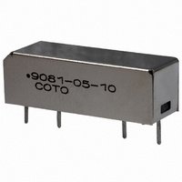
9081-05-10
Manufacturer Part Number
9081-05-10
Description
RELAY REED SPST .5A 5V SIP
Manufacturer
Coto Technology
Series
9000, Spartanr
Specifications of 9081-05-10
Relay Type
Reed
Circuit
SPST-NO (1 Form A)
Contact Rating @ Voltage
0.5A @ 200VAC/DC
Coil Type
Standard
Coil Current
10mA
Coil Voltage
5VDC
Control On Voltage (max)
3.75 VDC
Control Off Voltage (min)
0.4 VDC
Mounting Type
Through Hole
Termination Style
PC Pin
Coil Voltage Vdc Nom
5V
Coil Resistance
500ohm
Switching Current Max
500mA
Switching Voltage Max
200V
Contact Configuration
SPST
Relay Mounting
PCB
External Height
8.25mm
External Width
22.6mm
Rohs Compliant
Yes
Lead Free Status / RoHS Status
Lead free / RoHS Compliant
Other names
306-1138


Dot stamped on top of relay refers to pin #1
location.
COIL SPECS.
Nom. Coil Voltage
Max. Coil Voltage
Coil Resistance (standard)
Coil Resistance (hi-sensitivity)
Operate Voltage
Release Voltage
CONTACT RATINGS
Switching Voltage
Switching Current
Carry Current
Contact Rating
Life Expectancy-Typical
Static Contact
(max. init.)
Dynamic Contact
(max. init.)
RELAY
SPECIFICATIONS
Insulation Resistance
(minimum)
Capacitance - Typical
Across Open Contacts
Open Contact to Coil
Contact to Shield
Dielectric Strength (minimum)
Operate Time - including
bounce - Typical
Release Time - Typical
Model Number
Parameters
Notes:
1
2
3
4
5
9000 Series/Spartan SIP Reed Relays
Consult factory for life expectancy at other switching
Optional diode is connected to pin #2 (+) and pin
Consists of 20V Zener-diode and 1N1002 diode
For -40 and -50 models, 5V/1000 Ω or 12V/2000 Ω.
These relays contain bias magnets. Correct coil
#3(-). Correct coil polarity must be observed.
polarity must be observed. Pin #2(+)
in series, connected in parallel with coil.
loads.
For Most Recent Data, Consult the Coto Technology Website: www.cotorelay.com
Grid = .1"x.1" (2.54mm x 2.54mm)
Resistance
Resistance
1
Signal Level 1.0V, 1.0mA
Zener-Diode Suppression
Max DC/Peak AC Resist.
Max DC/Peak AC Resist.
Max DC/Peak AC Resist.
At Nominal Coil Voltage,
Max DC/Peak AC Resist.
Between all Isolated Pins
at 100V, 25°C, 40% RH
Contacts/Shield to Coil
Contacts Open, Shield
30 Hz Square Wave
at 100 Hz, 1.5 msec
Test Conditions
Between Contacts
Contacts to Shield
Must Operate by
Must Release by
Shield Guarding
Shield Guarding
Shield Floating
Shield Floating
+/- 10%, 25° C
50mV, 10mA
0.5V, 50mA
No Shield
No Shield
Floating
Top View:
4
VDC/peak AC
VDC/peak AC
VDC/peak AC
VDC - Max.
VDC - Min.
x 10
Units
VDC
VDC
Amps
Amps
Watts
msec.
msec.
Volts
Environmental Ratings
Storage Temp: -35°C to + 100°C;
Operating Temp: -20°C to + 85°C
Solder Temp: 270°C max; 10 sec. max
The operate and release voltage and the coil resistance are
specified at 25°C. These values vary by approximately
0.4%/°C as the ambient temperature varies.
Vibration: 20 G’s to 2000 Hz; Shock: 50 G’s
pF
pF
pF
pF
pF
pF
pF
Ω
Ω
Ω
Ω
Ω
6
Ops.
1000
500
3.75
6.5
0.4
5
.2 -.2 -.2 SIP
1000
2000
15.0
9007
12
9.0
1.0
x 10
0.200
1500
N/A
0.50
0.20
200
100
250
0.5
1.0
9007
1.4
10
0.7
-
-
-
-
-
-
10
2
2000
32.0
24
18.0
--
2.0
6
1000
500
3.75
6.5
0.4
9081
5
E-mail: sales@cotorelay.com
.2 -.4 -.2 SIP
1000
2000
15.0
x 10
9081
0.200
12
9.0
1.0
1500
0.50
0.20
N/A
200
100
250
0.5
1.0
1.4
10
0.7
-
-
-
-
-
-
10
2000
32.0
24
18.0
--
2.0
9081C
125
3.75
6.5
0.4
--
.2 -.2 -.2 -.2 SIP
.2 -.4 -.1 -.1 SIP
5
9081C
15.0
500
x 10
9081C1
0.200
12
9.0
1500
1.0
--
0.50
N/A
175
100
200
0.4
1.0
1.0
1.4
0.7
5
-
-
-
-
-
-
10
2000
32.0
24
18.0
--
2.0
37
Related parts for 9081-05-10
Image
Part Number
Description
Manufacturer
Datasheet
Request
R

Part Number:
Description:
RELAY REED 242 .5A 5VDC SIP
Manufacturer:
Coto Technology
Datasheet:
Part Number:
Description:
RELAY REED SIP SPST 5V MAGN SHLD
Manufacturer:
Coto Technology
Datasheet:

Part Number:
Description:
CIRCUIT PIN PRNTD .020"D .170"
Manufacturer:
Mill-Max Manufacturing Corp.
Datasheet:
Part Number:
Description:
RELAY REED 242 .5A 24VDC SIP
Manufacturer:
Coto Technology
Datasheet:
Part Number:
Description:
RELAY REED 242 .5A 12VDC SIP
Manufacturer:
Coto Technology
Datasheet:

Part Number:
Description:
RELAY REED SPST .5A 12V SIP
Manufacturer:
Coto Technology
Datasheet:
Part Number:
Description:
RELAY REED SIP SPST 12V
Manufacturer:
Coto Technology
Datasheet:

Part Number:
Description:
RELAY REED SPST .5A 24V SIP
Manufacturer:
Coto Technology
Datasheet:
Part Number:
Description:
RELAY REED SIP SPST 12V MAG SHLD
Manufacturer:
Coto Technology
Datasheet:

Part Number:
Description:
STANDARD P.C. BOARD PIN
Manufacturer:
Mill-Max Manufacturing Corp.
Part Number:
Description:
STANDARD P.C. BOARD PIN
Manufacturer:
Mill-Max Manufacturing Corp.

Part Number:
Description:
RELAY REED SPST W/DIODE 5VDC
Manufacturer:
Coto Technology
Datasheet:
Part Number:
Description:
RF Relays
Manufacturer:
COTO [Coto Technology]
Datasheet:
Part Number:
Description:
4-Channel RF Relays
Manufacturer:
COTO [Coto Technology]
Datasheet: