ARE134H Panasonic Electric Works, ARE134H Datasheet - Page 3
ARE134H
Manufacturer Part Number
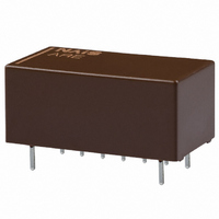
ARE134H
Description
RELAY 2.6GHZ .50A 4.5VDC PCB
Manufacturer
Panasonic Electric Works
Series
AREr
Datasheet
1.ARE134H.pdf
(5 pages)
Specifications of ARE134H
Relay Type
RF
Circuit
SPDT (1 Form C)
Contact Rating @ Voltage
0.5A @ 30VDC
Coil Type
Standard
Coil Current
44.4mA
Coil Voltage
4.5VDC
Control On Voltage (max)
3.38 VDC
Control Off Voltage (min)
0.45 VDC
Mounting Type
Through Hole
Termination Style
PC Pin
Lead Free Status / RoHS Status
Lead free / RoHS Compliant
Other names
255-1573
Available stocks
Company
Part Number
Manufacturer
Quantity
Price
Company:

Part Number:
ARE134H
Manufacturer:
AXICOM
Quantity:
12 000
Company:
Part Number:
ARE134HC03
Manufacturer:
OMRON
Quantity:
5 400


RE (ARE)
2. Specifications
Note: * The upper operation ambient temperature limit is the maximum temperature that can satisfy the coil temperature rise value. Refer to [6] AMBIENT ENVIRONMENT
REFERENCE DATA
1-(1). High frequency characteristics (Impedance 50Ω) (Standard PC board terminal)
• V.S.W.R. characteristics
Contact
Rating
High frequency
characteristics (Initial)
(Impedance 75Ω)
High frequency
characteristics (Initial)
(Impedance 50Ω)
Electrical
characteristics
Mechanical
characteristics
Expected life
Conditions
Unit weight
Characteristics
in GENERAL APPLICATION GUIDELINES.
1.9
1.8
1.7
1.6
1.5
1.4
1.3
1.2
1.1
1
900MHz
Arrangement
Contact material
Initial contact resistance, max.
Contact rating
Contact carrying power
Max. switching voltage
Max. switching current
Nominal operating power
V.S.W.R.
Insertion loss
Isolation
V.S.W.R.
Insertion loss
Isolation
Insulation resistance (Initial)
Breakdown
voltage
(Initial)
Temperature rise (at 20°C)
Operate time (at 20°C)
Release time (at 20°C)
Shock
resistance
Vibration
resistance
Mechanical
Electrical
Conditions for operation, transport and storage*
Frequency
COM-NO
COM-NC
Between open contacts
Between contact and coil
Between contact and earth terminal 500 Vrms for 1min. (Detection current: 10mA)
Functional
Destructive
Functional
Destructive
3GHz
Item
All Rights Reserved © COPYRIGHT Panasonic Electric Works Co., Ltd.
• Insertion loss characteristics
0.1
0.2
0.3
0.4
0.5
0.6
0.7
0.8
0.9
1.0
0
1 Form C
Gold plating
Max. 100mΩ (By voltage drop 10V AC 10mA)
1W (at 2.6 GHz [Impedance 75Ω;, V.S.W.R. Max.1.5] [Impedance 50Ω, V.S.W.R. Max.1.7])
10mA 24V DC (resistive load)
10W (at 2.6GHz [Impedance 75Ω, V.S.W.R. Max.1.5] [Impedance 50Ω, V.S.W.R. Max.1.7])
30V DC
0.5A DC
200mW
Max. 1.2 (to 900MHz), Max. 1.5 (to 2.6GHz)
Max. 0.2dB (to 900MHz), Max. 0.5dB (to 2.6GHz)
Min. 60dB (to 900MHz), Min. 30dB (to 2.6GHz)
Max. 1.3 (to 900MHz), Max. 1.7 (to 2.6GHz)
Max. 0.2dB (to 900MHz), Max. 0.7dB (to 2.6GHz)
Min. 60dB (to 900MHz), Min. 30dB (to 2.6GHz)
Min. 100MΩ (at 500V DC)
Measurement at same location as “Initial breakdown voltage” section.
500 Vrms for 1min. (Detection current: 10mA)
1,000 Vrms for 1min. (Detection current: 10mA)
Max. 60°C (By resistive method, nominal voltage applied to the coil: Contact carrying power:
10W, at 2.6GHz, [Impedance 75Ω, V.S.W.R.
Max. 10ms (Nominal operating voltage applied to the coil, excluding contact bounce time.)
Max. 5ms (Nominal operating voltage applied to the coil, excluding contact bounce time.)
(without diode)
Min. 500 m/s
Min. 1,000m/s
10 to 55 Hz at double amplitude of 3mm (Detection time: 10µs.)
10 to 55 Hz at double amplitude of 5mm
Min. 10
Min. 3×10
Min. 3×10
Ambient temperature: –40°C to +70°C
Humidity: 5 to 85% R.H. (Not freezing and condensing at low temperature)
Approx. 5 g
900MHz
6
(at 180 cpm)
5
5
Frequency
(1W, 2.6GHz, [Impedance 75Ω, V.S.W.R.
(10mA 24V DC (resistive load) (at 20cpm))
.18 oz
2
2
{50 G} (Half-wave pulse of sine wave: 11ms; detection time: 10µs.)
{100 G} (Half-wave pulse of sine wave: 6ms.)
COM-NC
COM-NO
3GHz
–40°F to +158°F
Specifications
• Isolation characteristics
1.5] [Impedance 50Ω, V.S.W.R.
100
10
20
30
40
50
60
70
80
90
0
1.5] [Impedance 50Ω, V.S.W.R.
900MHz
Frequency
COM-NC
COM-NO
1.7])
3GHz
1.7])
Related parts for ARE134H
Image
Part Number
Description
Manufacturer
Datasheet
Request
R

Part Number:
Description:
Manufacturer:
Panasonic Electric Works
Datasheet:
Part Number:
Description:
Manufacturer:
Panasonic Electric Works
Datasheet:

Part Number:
Description:
CONN SOCKET P4 .4MM 50POS SMD
Manufacturer:
Panasonic Electric Works
Datasheet:
Part Number:
Description:
CONN SOCKET .8MM 16POS SMD
Manufacturer:
Panasonic Electric Works
Datasheet:
Part Number:
Description:
CONN HEADER .8MM 16POS SMD
Manufacturer:
Panasonic Electric Works
Datasheet:
Part Number:
Description:
CONN SOCKET .8MM 20POS SMD
Manufacturer:
Panasonic Electric Works
Datasheet:
Part Number:
Description:
CONN SOCKET .8MM 20POS SMD
Manufacturer:
Panasonic Electric Works
Datasheet:
Part Number:
Description:
CONN HEADER .8MM 20POS SMD
Manufacturer:
Panasonic Electric Works
Datasheet:
Part Number:
Description:
CONN SOCKET .8MM 22POS SMD
Manufacturer:
Panasonic Electric Works
Datasheet:
Part Number:
Description:
CONN SOCKET .8MM 30POS SMD
Manufacturer:
Panasonic Electric Works
Datasheet:
Part Number:
Description:
CONN HEADER .8MM 30POS SMD
Manufacturer:
Panasonic Electric Works
Datasheet:
Part Number:
Description:
CONN SOCKET .8MM 30POS SMD
Manufacturer:
Panasonic Electric Works
Datasheet:
Part Number:
Description:
CONN SOCKET .8MM 30POS SMD
Manufacturer:
Panasonic Electric Works
Datasheet:
Part Number:
Description:
CONN HEADER .8MM 30POS SMD
Manufacturer:
Panasonic Electric Works
Datasheet:
Part Number:
Description:
CONN HEADER BRD/BRD .5MM 60POS
Manufacturer:
Panasonic Electric Works
Datasheet: