G6L-1P-DC4.5 Omron, G6L-1P-DC4.5 Datasheet - Page 8
G6L-1P-DC4.5
Manufacturer Part Number
G6L-1P-DC4.5
Description
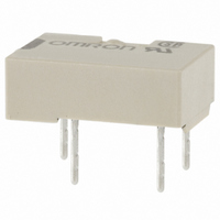
RELAY TELCOM SPST 4.5VDC PC MNT
Manufacturer
Omron
Series
G6Lr
Specifications of G6L-1P-DC4.5
Coil Type
Standard
Coil Current
40mA
Relay Type
Telecom
Circuit
SPST-NO (1 Form A)
Contact Rating @ Voltage
1A @ 24VDC
Coil Voltage
4.5VDC
Control On Voltage (max)
3.38 VDC
Control Off Voltage (min)
0.45 VDC
Mounting Type
Through Hole
Termination Style
PC Pin
Contact Form
1 Form C
Power Consumption
180 mW
Maximum Switching Current
1 A
Contact Rating
0.3 A at 125 VAC, 1 A at 24 VDC
Contact Configuration
SPST-NO
Contact Current Max
1A
Contact Voltage Ac Nom
125V
Contact Voltage Dc Nom
24V
Coil Voltage Vdc Nom
4.5V
Current, Rating
0.3⁄1 AAC⁄ADC
Dielectric Rating
1000 VAC @ 50⁄60 Hz for 1 Minute (Coil and Contacts), 750 VAC @ 50⁄60 Hz for 1 Minute (Contacts of Same Poles)
Dimensions
10.6 mm L x 7 mm W x 3.8 mm H
Function
General Purpose
Material, Contact
Ag (Au-Clad)
Number Of Pins
4
Standards
UL, CSA, FCC, RoHS
Temperature, Operating, Maximum
70 °C
Temperature, Operating, Minimum
-40 °C
Termination
Through Hole
Voltage, Control
4.5 VDC
Voltage, Rating
125 VAC
Lead Free Status / RoHS Status
Lead free / RoHS Compliant
Lead Free Status / RoHS Status
Lead free / RoHS Compliant, Lead free / RoHS Compliant
Other names
G6L1PDC4.5
G6L1PDC45
Z1227
G6L1PDC45
Z1227
Available stocks
Company
Part Number
Manufacturer
Quantity
Price
Company:

Part Number:
G6L-1P-DC4.5V
Manufacturer:
FUJITSU
Quantity:
12 000


Precautions
■ Correct Use
Long-term Continuously ON Contacts
Using the Relay in a circuit where the Relay will be ON continuously
for long periods (without switching) can lead to unstable contacts
because the heat generated by the coil itself will affect the insulation,
causing a film to develop on the contact surfaces. Be sure to use a
fail-safe circuit design that provides protection against contact failure
or coil burnout.
Handling
Leave the Relays packed until just prior to mounting them.
Soldering
Solder: JIS Z3282, H63A
Soldering temperature: Approx. 250°C (At 260ºC if the DWS method
is used.)
Soldering time: Approx. 5 s max. (approx. 2 s for the first time and
approx. 3 s for the second time if the DWS method is used.)
Be sure to adjust the level of the molten solder so that the solder will
not overflow onto the PCB.
Claw Securing Force During Automatic
Insertion
During automatic insertion of Relays, make sure to set the securing
force of the claws to the following values so that the Relay character-
istics will be maintained.
Environmental Conditions During Operation,
Storage, and Transportation
Protect the Relays from direct sunlight and keep the Relays under
normal temperature, humidity, and pressure.
44
Secure the claws to the area indicated by shading.
Do not attach them to the center area or to only part of the
Relay.
Low Signal Relay
A
Direction A: 5.0 N max.
Direction B: 5.0 N max.
Direction C: 5.0 N max.
C
G6L
B
Maximum Voltage
The maximum voltage of the coil can be obtained from the coil tem-
perature increase and the heat-resisting temperature of coil insulat-
ing sheath material. (Exceeding the heat-resisting temperature may
result in burning or short-circuiting). The maximum voltage also
involves important restrictions which include the following:
• Must not cause thermal changes in or deterioration of the insulating
• Must not cause damage to other control devices.
• Must not cause any harmful effect on people.
• Must not cause fire.
Therefore, be sure not to exceed the maximum voltage specified in
the catalog.
As a rule, the rated voltage must be applied to the coil. A voltage
exceeding the rated value, however, can be applied to the coil pro-
vided that the voltage is less than the maximum voltage. It must be
noted that continuous voltage application to the coil will cause a coil
temperature increase thus affecting characteristics such as electrical
life and resulting in the deterioration of coil insulation.
Coating
Relays mounted on PCBs may be coated or washed. Do not apply
silicone coating or detergent containing silicone, otherwise the sili-
cone coating or detergent may remain on the surface of the Relays.
Coil Power Supply Waveform
If the voltage applied to the coil is increased or decreased gradually,
operating characteristics may be unstable, contact endurance may
decline, or the Relay may not function at its full performance level.
Therefore, always use an instantaneous ON and instantaneous OFF
when applying the voltage. Be sure that the rated voltage or zero
voltage is reached within 1 ms.
material.
Related parts for G6L-1P-DC4.5
Image
Part Number
Description
Manufacturer
Datasheet
Request
R

Part Number:
Description:
LOW SIGNAL RELAY
Manufacturer:
Omron
Datasheet:
Part Number:
Description:
LOW SIGNAL RELAY
Manufacturer:
Omron
Datasheet:

Part Number:
Description:
Low Signal Relays - PCB LO PROF SPST 5VDC
Manufacturer:
Omron
Datasheet:
Part Number:
Description:
Low Signal Relays - PCB LO PROF SPST 12VDC
Manufacturer:
Omron
Datasheet:
Part Number:
Description:
RELAY TELCOM SPST 3VDC PC MNT
Manufacturer:
Omron
Datasheet:
Part Number:
Description:
RELAY TELCOM SPST 24V PCB
Manufacturer:
Omron
Datasheet:

Part Number:
Description:
RELAY, PCB, SPNO, 24VDC
Manufacturer:
Omron
Datasheet:
Part Number:
Description:
RELAY, PCB, SPNO, 3VDC
Manufacturer:
Omron
Datasheet:
Part Number:
Description:
RELAY, PCB, SPNO, 5VDC
Manufacturer:
Omron
Datasheet:

Part Number:
Description:
RELAY, SMD, SPNO, 12VDC
Manufacturer:
Omron
Datasheet: