G2-2A03-TT Crydom Co., G2-2A03-TT Datasheet
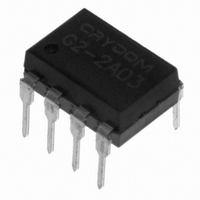
G2-2A03-TT
Specifications of G2-2A03-TT
G2-2A03-TT


Related parts for G2-2A03-TT


G2-2A03-TT Summary of contents
Page 1
... For recommended applications and more information contact: USA: Sales Support (877) 502-5500 Tech Support (877) 702-7700 FAX (619) 710-8540 Crydom Corp, 2320 Paseo de las Americas, Ste. 201, San Diego, CA 92154 Email: sales@crydom.com WEB SITE: http://www.crydom.com G2 Series/ Solid State Relays Sym. Test Conditions ...
Page 2
... G2 Series/ 250 200 150 100 G2-2A03 I( -40 - Temperature (Deg C) A. Load Current vs. Ambient Temperature 240% G2-2A03 I( 190% I( 140% 90% 40% -10% -60% -40 - Temperature (Deg Time vs. Ambient Temperature 5000 deg. C 4000 I( 3000 2000 1000 LED Forward Current (mA) F. Turn On Time vs. LED Forward Current For recommended applications and more information contact: USA: Sales Support (877) 502-5500 Tech Support (877) 702-7700 FAX (619) 710-8540 Crydom Corp, 2320 Paseo de las Americas, Ste ...