G3VM-6 Omron, G3VM-6 Datasheet - Page 2
G3VM-6
Manufacturer Part Number
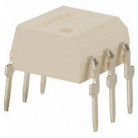
G3VM-6
Description
RELAY SSR SPST 150MA 6-DIP
Manufacturer
Omron
Series
G3VMr
Specifications of G3VM-6
Circuit
SPST-NO (1 Form A)
Output Type
AC, DC
On-state Resistance
12 Ohm
Load Current
150mA
Voltage - Input
1.15VDC
Voltage - Load
0 ~ 400 V
Mounting Type
Through Hole
Termination Style
PC Pin
Package / Case
6-DIP (0.300", 7.62mm)
Control Voltage Range
1.2 V to 1.7 V
Load Voltage Rating
400 V
Load Current Rating
150 mA
Contact Form
SPST - NO
Output Device
MOSFET
Mounting Style
PCB
Relay Type
MOSFET Relay
Turn-on Switching
FET
Lead Free Status / RoHS Status
Lead free / RoHS Compliant
Lead Free Status / RoHS Status
Lead free / RoHS Compliant, Lead free / RoHS Compliant
Other names
G3VM-6-S
G3VM6S
Z158
G3VM6S
Z158
Available stocks
Company
Part Number
Manufacturer
Quantity
Price

Part Number:
G3VM-6
Manufacturer:
OMRON/欧姆龙
Quantity:
20 000
Part Number:
G3VM-601AY1
Manufacturer:
OMRON/欧姆龙
Quantity:
20 000
Company:
Part Number:
G3VM-601BY
Manufacturer:
GOODSKY
Quantity:
12 000
Company:
Part Number:
G3VM-601EY
Manufacturer:
MXIC
Quantity:
343
Company:
Part Number:
G3VM-601EY(TR)
Manufacturer:
OMRON
Quantity:
12 000
Part Number:
G3VM-601G1
Manufacturer:
OMRON/欧姆龙
Quantity:
20 000
Company:
Part Number:
G3VM-61A
Manufacturer:
Omron Electronics
Quantity:
135
Part Number:
G3VM-61A
Manufacturer:
OMRON/欧姆龙
Quantity:
20 000
Company:
Part Number:
G3VM-61A1
Manufacturer:
OMRON
Quantity:
12 000
Part Number:
G3VM-61AY1
Manufacturer:
OMRON/欧姆龙
Quantity:
20 000


G3VM-6(F)
Specifications
Note: 1. The output load current varies depending on the ambient temperature. Refer to Engineering Data .
Note: Switching Time Measuring Circuit
Input
Output
Ambient temperature (with no icing or condensation)
Storage temperature (with no icing or condensation)
Soldering temperature (10 s)
Output ON resistance
Ou pu O
Current leakage when the relay is closed
LED forward voltage
Capacity between I/O terminals
Insulation resistance between I/O
terminals
Operating time
Release time
Connection diagram
Absolute Maximum Ratings (Ta = 25 C)
Electrical Characteristics (Ta = 25 C)
Connection A
2. The dielectric strength was checked for each connection by applying a voltage between each pairing of pins 1, 2, and 3 and pins 4, 5,
Load
and 6.
LED forward current
Repetitive peak LED forward current
(Duty: 1% max.; pulse width: 100 s max.)
LED reverse voltage
Output dielectric strength (see
note 2)
Continuous load current (see
Co
note 1)
Dielectric strength between I/O terminals (AC for 1 min,
operating ambient humidity
es s a ce
t 1)
)
uous oad cu e
Connection B
Item
Load
Connection A
Connection B
Connection C
Connection C
Item
(see
Load
60%) (see note 2)
Connection A
Connection B
Connection C
Connection A
Connection B
Connection C
R
I
V
C
R
T
T
LEAK
Symbol
ON
OFF
ON
ON
F
I-O
I-O
---
---
---
---
1.2
---
5 x 10
---
---
Minimum
10
---
---
---
---
1.4
0.8
---
---
---
Typical
I
I
V
V
V
I
V
Ta
Tstg
---
F
FP
O
O
Symbol
R
BO
BO
BO
I–O
12
6
3
1.0
1.7
---
---
1
1
Maximum
30
1
5
DC or AC peak
value: –400 to 400
DC: 0 to 400
150
200
300
5,000
–40 to +85
–55 to +125
260
C 0 o 00
V
pF
ms
ms
Ratings
A
Unit
I
V
I
f=1 MHz
V
V
I
R
I
R
F
F
F
F
F
ON
F
I-O
L
L
=10 mA, I
=10 mA
=10 mA, V
=10 mA, V
=0, V
=200
=200
=500 VDC
0
=V
Measurement
mA
A
V
V
V
mA
Vrms
C
C
C
conditions
BO
G3VM-6(F)
0
=0,
,
(see note)
(see note)
ON
ON
Unit
DD
DD
=100 mA
=20 V,
=20 V,
00
45
Related parts for G3VM-6
Image
Part Number
Description
Manufacturer
Datasheet
Request
R

Part Number:
Description:
RELAY SSR SPST 150MA 4-SOP
Manufacturer:
Omron
Datasheet:

Part Number:
Description:
RELAY SSR SPST 120MA 4-SOP
Manufacturer:
Omron
Datasheet:

Part Number:
Description:
SSR, MOSFET, 350V, 120mA
Manufacturer:
Omron
Datasheet:
Part Number:
Description:
RELAY SSR SPST 60V 400MA 4SOP
Manufacturer:
Omron
Datasheet:
Part Number:
Description:
RELAY SSR SPST 40VAC 300MA 4SOP
Manufacturer:
Omron
Datasheet:

Part Number:
Description:
SSR, MOSFET, 350V, 100mA
Manufacturer:
Omron
Datasheet:

Part Number:
Description:
RELAY SSR SPST 120MA 6-SOP
Manufacturer:
Omron
Datasheet:

Part Number:
Description:
RELAY SSR DPST 120MA 8-SMT
Manufacturer:
Omron
Datasheet:

Part Number:
Description:
RELAY SSR DPST 300MA 8-SOP
Manufacturer:
Omron
Datasheet:

Part Number:
Description:
Relay (Solid-State)
Manufacturer:
Omron
Datasheet:
Part Number:
Description:
Relay (Solid-State)
Manufacturer:
Omron
Datasheet:
Part Number:
Description:
MOSFET SMT Tape And Reel Relay
Manufacturer:
Omron
Datasheet:
Part Number:
Description:
MOSFET SSOP Tape&Reel - 500pcs
Manufacturer:
Omron
Datasheet:
Part Number:
Description:
MOSFET SSOP Tape & Reel-500pcs
Manufacturer:
Omron
Datasheet:
Part Number:
Description:
MOSFET SMT RELAY
Manufacturer:
Omron
Datasheet: