G3VM-S2 Omron, G3VM-S2 Datasheet - Page 68
G3VM-S2
Manufacturer Part Number
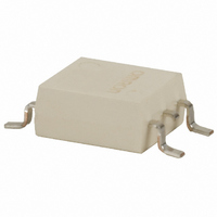
G3VM-S2
Description
RELAY SSR SPST 120MA 4-SOP
Manufacturer
Omron
Series
G3VMr
Specifications of G3VM-S2
Load Current
120mA
Circuit
SPST-NO (1 Form A)
Output Type
AC, DC
On-state Resistance
35 Ohm
Voltage - Input
1.15VDC
Voltage - Load
0 ~ 350 V
Mounting Type
Surface Mount
Termination Style
Gull Wing
Package / Case
4-SOP
Control Voltage Range
1 V to 1.3 V
Load Voltage Rating
350 V
Off State Leakage Current (max)
1 uA
Load Current Rating
120 mA
Contact Form
1 Form A
Output Device
MOSFET
Mounting Style
SMD/SMT
Relay Type
MOSFET Relay
Turn-on Switching
FET
Load Voltage Max
350VAC
On State Resistance Max
35ohm
Contact Configuration
SPST-NO
Isolation Voltage
1500Vrms
Forward Current If
7.5mA
Relay Terminals
SMD
Load Current Rms Max
110mA
Rohs Compliant
Yes
Lead Free Status / RoHS Status
Lead free / RoHS Compliant
Lead Free Status / RoHS Status
Lead free / RoHS Compliant, Lead free / RoHS Compliant
Other names
G3VM-S2-S
G3VMS2
Z160
G3VMS2
Z160
Available stocks
Company
Part Number
Manufacturer
Quantity
Price

Part Number:
G3VM-S2-S
Manufacturer:
OMRON/欧姆龙
Quantity:
20 000


G3VM-41LR4, -41LR5, -41LR6
Maximum Rating
Electrical Characteristics
Optimum Operating Conditions
90
Contact form/no. of terminals
Input (LED)
Output
(Detector)
Dielectric strength
Temperature
Input
Output
Transfer
characteristics
Output voltage strength
Operate LED forward current
Continuous load current
Ambient temperature
MOS FET Relays
Parameter
Parameter
Parameter
LED forward current
Forward current
derating
Reverse voltage
Junction temperature (T
Output voltage
strength
Continuous load
current
ON-state current
derating
Junction temperature (T
Ambient
Storage
LED forward voltage
(V
Reverse current
Reverse voltage
Capacitance (C
Keep ON LED current
(I
ON-resistance (R
OFF-state leakage
current (I
Limit current (I
I/O capacitance
I/O resistance
Operate time
Release time
FT
F
)
)
LEAK
)
LIM
T
)
)
ON
G3VM Series
)
—
I
I
100 pps)
Ta ≥ 25°C
V
V
I
Ta ≥ 25°C
V
Ta with no icing
Tstg with no icing
I
I
V
V = 0;
freq. = 1 MHz
At I
At I
At V
I
V, t = 5 ms
(C
(R
(t
(t
V
I
I
T
F
FP
O
F
R
F
F
O
Comments and conditions G3VM-41LR4
J
J
Comments and conditions G3VM-41LR4
Comments and conditions G3VM-41LR4
A
R
OFF
I/O
R
ON
OFF
DD
=10 mA
)
)
= 5 mA, V
I/O
IO
(100 µs pulse,
ON
O
)
)
for 1 minute min.
OFF
)
)
DD
= 5
Typical
Max.
Max.
Min.
Typical
Max.
Max.
Max.
Typical
Typical
Max.
Typical
Max.
Max.
Min.
Max.
Typical
Min.
Max.
Max.
Max.
Min.
Typical
Max.
Max.
1 Form A/4 pins
50 mA
1 A
-0.5 mA/°C
5 V
125°C
40 V
250 mA
-2.5 mA/°C
125°C
1500 VAC
-20° to +85°C
-40° to +125°C
1.0 V
1.15 V
1.3 V
10 µA
5 V
15 pF
—
4 mA (I
2 Ω (I
3 Ω (I
1.0 nA
5 pF
7 pF
0.8 pF
1000 MΩ
0.5 ms
0.5 ms
32 V
10 mA
—
30 mA
250 mA
-25° to 60°C
ON
ON
ON
=250 mA)
=250 mA)
=100 mA)
G3VM-41LR5
1 Form A/4 pins
50 mA
1 A
-0.5 mA/°C
5 V
125°C
40 V
300 mA
-3.0 mA/°C
125°C
1500 VAC
-20° to +85°C
-40° to +125°C
G3VM-41LR5
1.0 V
1.15 V
1.3 V
10 µA
5 V
15 pF
—
4 mA (I
1.0 Ω (I
1.5 Ω (I
1.0 nA
10 pF
14 pF
0.8 pF
1000 MΩ
0.5 ms
0.5 ms
G3VM-41LR5
32 V
10 mA
—
30 mA
300 mA
-25° to 60°C
ON
ON
ON
=100 mA)
=300 mA)
=300 mA)
G3VM-41LR6
1 Form A/4 pins
50 mA
1 A
-0.5 mA/°C
5 V
125°C
40 V
120 mA
-1.2 mA/°C
125°C
1500 VAC
-20° to +85°C
-40° to +125°C
G3VM-41LR6
1.0 V
1.15 V
1.3 V
10 µA
5 V
15 pF
—
4 mA (I
10 Ω (I
15 Ω (I
1.0 nA
1.0 pF
2.0 pF
0.8 pF
1000 MΩ
0.5 ms
0.5 ms
G3VM-41LR6
32 V
10 mA
—
30 mA
120 mA
-25° to 60°C
ON
ON
ON
=120 mA)
=120 mA)
=100 mA)
Related parts for G3VM-S2
Image
Part Number
Description
Manufacturer
Datasheet
Request
R

Part Number:
Description:
RELAY SSR SPST 150MA 4-SOP
Manufacturer:
Omron
Datasheet:

Part Number:
Description:
SSR, MOSFET, 350V, 120mA
Manufacturer:
Omron
Datasheet:

Part Number:
Description:
RELAY SSR SPST 60V 400MA 4SOP
Manufacturer:
Omron
Datasheet:
Part Number:
Description:
RELAY SSR SPST 40VAC 300MA 4SOP
Manufacturer:
Omron
Datasheet:

Part Number:
Description:
SSR, MOSFET, 350V, 100mA
Manufacturer:
Omron
Datasheet:

Part Number:
Description:
RELAY SSR SPST 120MA 6-SOP
Manufacturer:
Omron
Datasheet:

Part Number:
Description:
RELAY SSR DPST 120MA 8-SMT
Manufacturer:
Omron
Datasheet:

Part Number:
Description:
RELAY SSR SPST 150MA 6-DIP
Manufacturer:
Omron
Datasheet:

Part Number:
Description:
RELAY SSR DPST 300MA 8-SOP
Manufacturer:
Omron
Datasheet:

Part Number:
Description:
Relay (Solid-State)
Manufacturer:
Omron
Datasheet:
Part Number:
Description:
Relay (Solid-State)
Manufacturer:
Omron
Datasheet:
Part Number:
Description:
MOSFET SMT Tape And Reel Relay
Manufacturer:
Omron
Datasheet:
Part Number:
Description:
MOSFET SSOP Tape&Reel - 500pcs
Manufacturer:
Omron
Datasheet:
Part Number:
Description:
MOSFET SSOP Tape & Reel-500pcs
Manufacturer:
Omron
Datasheet:
Part Number:
Description:
MOSFET SMT RELAY
Manufacturer:
Omron
Datasheet: