MC22FF102J Cornell Dubilier Electronics (CDE), MC22FF102J Datasheet - Page 7
MC22FF102J
Manufacturer Part Number
MC22FF102J
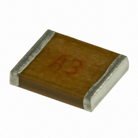
Description
CAP 1000PF 1000V MICA CHIP 2220
Manufacturer
Cornell Dubilier Electronics (CDE)
Series
MCr
Specifications of MC22FF102J
Capacitance
1000pF
Package / Case
2220 (5750 Metric)
Voltage - Rated
1000V (1kV)
Tolerance
±5%
Dielectric Material
Mica
Mounting Type
Surface Mount
Operating Temperature
-55°C ~ 125°C
Features
RF, High Q, Low Loss
Size / Dimension
0.224" L x 0.197" W (5.70mm x 5.00mm)
Height
0.157" (4.00mm)
Tolerance (+ Or -)
5%
Voltage
1000VDC
Mounting Style
Surface Mount
Construction
SMT Chip
Lead Spacing (nom)
Not Requiredmm
Military Standard
Not Required
Failure Rate
Not Required
Product Length (mm)
5.7mm
Product Depth (mm)
5mm
Product Height (mm)
2mm
Product Diameter (mm)
Not Requiredmm
Lead Diameter (nom)
Not Requiredmm
Seated Plane Height
Not Requiredmm
Operating Temp Range
-55C to 125C
Lead Free Status / RoHS Status
Contains lead / RoHS non-compliant
Lead Spacing
-
Lead Free Status / RoHS Status
Not Compliant, Contains lead / RoHS non-compliant
Other names
338-1035
Available stocks
Company
Part Number
Manufacturer
Quantity
Price
Company:

Part Number:
MC22FF102J-F
Manufacturer:
Cornell Dubilier Electronics (
Quantity:
135


CDE Cornell Dubilier • 1605 E. Rodney French Blvd. • New Bedford, MA 02744 • Phone: (508)996-8561 • Fax: (508)996-3830 • www.cde.com
CDE Cornell Dubilier • 1605 E. Rodney French Blvd. • New Bedford, MA 02744 • Phone: (508)996-8561 • Fax: (508)996-3830 • www.cde.com
Specifications
Quality Factor (Q)
lows when measured at 1 MHz
Insulation Resistance
than 100 GΩ when measured at 100
Vdc
Withstanding voltage
times the rated voltage between 5
seconds and without damage: with
50 mA or less current.
Life Test:
125 ºC ±3 ºC with 1.5 times rated
voltage applied for 2000 (+72, –0)
hours. There will be no visual dam-
age and the capacitors will meet the
limits of the table below.
Vibration Resistance:
the capacitors to simple harmonic
motion with an amplitude of 0.06
inches; vary the frequency uniformly
from 10 to 55 Hz and return to 10 Hz,
all in one minute. Repeat that cycle
continuously for two hours in
After-Test Limits
Vibration Resistance
Capacitance
Solder Heat Res.
Heat Resistance
1 to 80 pF
Moisture Res.
Bending Test
Solderability
>80 pF
Range
Life Test
Test
Subject capacitors to
500 to 3000
Min. Q
Withstand
is as fol-
3000
Voltage
is no less
Subject
IL
IL
IL
IL
IL
IL
is two
Types MC and MCN
Moisture Resistance:
the capacitors to 40 ±2 ºC at 90 to
95% humidity for 500 (+24, –0)
hours. Return to room ambient for
24 hours. There will be no visual
damage and the capacitors will meet
the limits of the table below.
each of three mutually perpendicular
directions. There will be no visual
damage and the capacitors will meet
the limits of the table below.
B
tor as shown below and press the ram
bar until a 2.0 mm deflection is
achieved. There will be no visual
damage and the capacitors will meet
the limits of methods JIS 5102 8.11
and AEC-Q200-005 without crack-
ing or visual damage.
ending Test:
Resistance
Insulation
30 GΩ
30 GΩ
30 GΩ
5 GΩ
IL
IL
7
Mount the capaci-
(whichever >)
Capacitance
IV ±2% or ±.5 pF
IV ±.5% or ±1 pF
IV ±3% or ±.5 pF
IV ±.5% or ±1 pF
IV ±1% or ±1 pF
Subject
IL
Multilayer RF Capacitors
Temperature Coefficient and
Drift:
pacitance at 25 ºC, –55 ºC, 25 ºC, 125
ºC and at 25 ºC — all ±3 ºC — after
stabilizing at each temperature. The
capacitor will meet the limits of the
Characteristic table in Ordering In-
formation.
Heat Resistance:
capacitors to 125 ±2 ºC for 2 (+1,–0)
hours. Then the insulation resistance
will be no less than 5GΩ.
Solderability:
onds in molten solder with Sn-PB
between molten and solder at 235 ±5
ºC, solder coverage will be no less
than 75% when examined at 10X
magnification for flow soldering.
Solder Heat Resistance:
ject the capacitors to molten solder
at 250±5 ºC for 5±0.5 seconds after
10 to 30 seconds pre-heating at 80
to 120 ºC. There will be no visual
damage and the capacitors will meet
the limits of the table below.
Measure the capacitors’ ca-
150% max IL
150% max IL
DF
IL
IL
IL
IL
After 2 ±0.5 sec-
Subject the
2/3 x IL
2/3 x IL
Q
IL
IL
IL
Sub-
Related parts for MC22FF102J
Image
Part Number
Description
Manufacturer
Datasheet
Request
R

Part Number:
Description:
CONTACTOR, 1NO, 110VAC, 22A, DIN RAIL
Manufacturer:
IMO PRECISION CONTROLS
Datasheet:
Part Number:
Description:
CONTACTOR, 1NO, 230VAC, 22A, DIN RAIL
Manufacturer:
IMO PRECISION CONTROLS
Datasheet:
Part Number:
Description:
CONTACTOR, 1NO, 24VAC, 22A, DIN RAIL
Manufacturer:
IMO PRECISION CONTROLS
Datasheet:


Part Number:
Description:
CAP 2200PF 50V FILM 5% 0805
Manufacturer:
Cornell Dubilier Electronics (CDE)
Datasheet:

Part Number:
Description:
CAP 1.0UF 100V FILM 10% 3925
Manufacturer:
Cornell Dubilier Electronics (CDE)
Datasheet:

Part Number:
Description:
CAP ALUM 16UF 450V AXIAL
Manufacturer:
Cornell Dubilier Electronics (CDE)
Datasheet:

Part Number:
Description:
CAP ALUM 160UF 250V AXIAL
Manufacturer:
Cornell Dubilier Electronics (CDE)
Datasheet:
Part Number:
Description:
CAP 6200UF 300V ELECT SCREW TERM
Manufacturer:
Cornell Dubilier Electronics (CDE)
Datasheet:

Part Number:
Description:
Multilayer Ceramic Capacitors (MLCC) - Leaded MONO CAP 50V .33uF
Manufacturer:
Cornell Dubilier Electronics (CDE)
Datasheet:

Part Number:
Description:
CAP PP FILM 1µF, 1.2KV, AXIAL
Manufacturer:
Cornell Dubilier Electronics (CDE)
Datasheet:
Part Number:
Description:
SMT-POL/AL(SPA
Manufacturer:
Cornell Dubilier Electronics (CDE)
Datasheet:

Part Number:
Description:
Encoders 8 OHM T-PAD WW ATTEN
Manufacturer:
Cornell Dubilier Electronics (CDE)
Datasheet:

Part Number:
Description:
CAPACITOR CERAMIC, 0.1UF, 50V, X7R, 1206
Manufacturer:
Cornell Dubilier Electronics (CDE)
Datasheet: