H5F-KB Omron, H5F-KB Datasheet
H5F-KB
Specifications of H5F-KB
Available stocks


Related parts for H5F-KB


H5F-KB Summary of contents
Page 1
... Screw terminals Accessories (Order Separately) Soft cover Hard cover Flush Mounting Adapter (See note 2.) Mounting Track End Plate Spacer Note: 1. Supplied with H5F-KB model. 2. Supplied with H5F-B (flush-mounting) model. Mounting method Flush mounting Surface mounting Surface mounting/track mounting Name For H5F-B For H5F-FB/- (l) ´ ...
Page 2
... Light gray (Munsell 5Y7/1) Weight H5F-B: approx. 115 g; H5F-KB: approx. 160 g; H5F-FB: approx. 130 g Note: 1. The total error including the repeat accuracy, setting error, variation due to voltage change, and variation due to temperature change is ± 0.01% ± 0.05 s max. ± 0.01% also indicates an error in the time interval of a set time. ...
Page 3
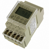
... Time range Operation Display Other functions Number of circuits Minimum setting unit Minimum set interval Number of operations that can be set Note ON/OFF operations are possible per day. (For pulse-output operation, the number is 24.) H5F-KB (Front View) TIME SWITCH H5F 5 00 TIME SWITCH ...
Page 4
... It is possible to set a day in the present week as a holiday (i.e., a non-operation day: output OFF regardless of the settings). When that day has passed, operation will continue according to the regular program, and operation will be executed as normal on that day from the follow- ing week • This function can be used with pulse-output operation. H5F ...
Page 5
... Displays hday (hday) when the Holiday setting mode: Time Switch is in holiday setting mode. Displays test (test) during Program check: program check. Function Pulse Width Unit Indicator Summer Time Indicator Lit when set to summer time. Digital Daily Time Switch H5F 5 ...
Page 6
... POW TMR / AUT O CLR OFF SE LEC +1h HO LID AY 92 TES T 100 to 240V AC 50/6 0Hz 15A 1 2.4V A max 250V 10A 24VD C 3 RES . 4 H5F-KB (Surface/Track Mounting TIM E SW ITC 101 POW TMR / AUT O CLR SE LEC T OFF +1h HO LID AY TES T 1 2.4V A max 2 . ...
Page 7
... PFP-100N, PFP-50N 4 1,000 (500) (see note) Note: The values shown in parentheses are for the PFP-50N. End Plate PFP-M 50 11.5 10 Hard Cover (provided with H5F-KB) Y92F-48 (for H5F-B) Y92A-48E (for H5F-FB/-KB) PFP-100N2 7.3±0.15 4.5 27±0.15 35±0 Spacer PFP-S 10 6.2 1.8 1 35.5 35.3 1 ...
Page 8
... Store at the specified temperature. If the H5F has been stored at a Circuit temperature of less than - 10 ° C, allow the H5F to stand at room H5F temperature for at least 3 hours before use. • This Time Switch is not waterproof or oil-proof. Do not use it in locations where water or oil may enter the Time Switch interior. • ...
Page 9
... Precautions for EN61010-1 Conformance The H5F Time Switch conforms to EN61010-1 provided that the fol- lowing conditions are satisfied: Basic insulation is provided between the power supply and output terminals of the H5F. • Output terminals are connected to devices without exposed charged parts. • Output terminals are connected to devices with basic insulation that is suitable for the maximum operating voltage ...
Page 10
... ON PW not both) is set, the operation set- ting time display will flash to indi- cate an error Set the OFF time to 5:15 pm using AM the ON PW H5F Key. The colon WRITE Key 3 times to MODE Display of factory setting Key for 1 s min ...
Page 11
... PW 2. Switching between timer operation and pulse-output oper- ation will clear the operation start time, operation day, and pulse width settings. 3. Both the timer operation and pulse-output operation can- not be programmed together. Digital Daily Time Switch The color indicates flashing H5F 11 ...
Page 12
... Press the The Time Switch will enter run mode and operation will start Note: Operation based on the changed settings will start as soon as H5F symbol to Saturday Key. Make the d Key. Move the WRITE Key. Clear the d Key. WRITE Lit: Operation day Not lit: Non-operation day Flashing: Specified operation day Key ...
Page 13
... The color indicates flashing Key. The ON time for MODE Key twice. The WRITE Key. (Both the ON CLR Key twice. The MODE The color indicates flashing Key. MODE Key for 3 s min. CLR H5F Digital Daily Time Switch Key is re- CLR 13 ...
Page 14
... Use the following procedure to stop operation at 3: for the present day only displayed while +1h Regular program Override and automatic return operation ON Output H5F Key is pressed for 2 s min. in run mode, the min The factory setting is 12-hour (am/pm) display. time on the present day only ON at 8:30 am ...
Page 15
... The ON and OFF symbols ( / program check have no effect on the present operation. 4. Only ON times are displayed for pulse-output operation. H5F Digital Daily Time Switch From the next time onwards, output operates according to the regular program ...
Page 16
Setting Examples As shown in the following examples, continuous operation for more than 24 hours is possible by combining two or more settings. Refer to Setting Precautions for more details. Example 1: Use the settings given below to turn ON ...
Page 17
... Cancellation; Etc. Orders are not subject to rescheduling or cancellation unless Buyer indemnifies Omron against all related costs or expenses. 10. Force Majeure. Omron shall not be liable for any delay or failure in delivery resulting from causes beyond its control, including earthquakes, fires, floods, strikes or other labor disputes, shortage of labor or materials, accidents to machinery, acts of sabotage, riots, delay in or lack of transportation or the requirements of any government authority ...
Page 18
... Complete “Terms and Conditions of Sale” for product purchase and use are on Omron’s website at www.omron247.com – under the “About Us” tab, in the Legal Matters section. ALL DIMENSIONS SHOWN ARE IN MILLIMETERS. To convert millimeters into inches, multiply by 0.03937. To convert grams into ounces, multiply by 0.03527. ...