766143102G CTS Resistor Products, 766143102G Datasheet
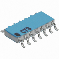
RES NET 7RES 1K OHM 14PIN SMD

766143102G

Manufacturer Part Number
766143102G
Description
RES NET 7RES 1K OHM 14PIN SMD
Manufacturer
CTS Resistor Products
Series
766r
Datasheet

Specifications of 766143102G

Resistance (ohms)
1K
Number Of Resistors
7
Circuit Type
Isolated
Temperature Coefficient
±100ppm/°C
Tolerance
±2%
Power Per Element
160mW
Number Of Pins
14
Package / Case
14-SOIC (0.154", 3.90mm Width)
Size / Dimension
0.341" L x 0.154" W (8.65mm x 3.90mm)
Height
0.061" (1.55mm)
Mounting Type
Surface Mount
Operating Temperature
-55°C ~ 125°C
Lead Free Status / RoHS Status
Contains lead / RoHS non-compliant
Other names
766-143-102
766-143-R1K
Document No. 008-0348-0
ORDERING INFORMATION
FEATURES
• Narrow Body Design
• Surface Mount Gull Wing Design
• Solid Ceramic Construction
• No Internal Dendrite Growth
• Requires 30% Less Board Space than Molded Products
• Meets EIA PDP SOGN-0001 Outline
• Application Specific Circuits are Available
• Compatible with Solder Reflow Process
• Tape and Reel Packaging or Slide Packs
Notes:
1. No dashes or spaces to appear in part number.
2. Example Part Numbers;
RoHS Compliant in Accordance with EU Directive 2005/95/EC
[Codes are 3 - 4 characters.]
1 - Bussed Circuit
3 - Isolated Circuit
5 - Dual Terminator Circuit
7 - Ladder
Refer to tables on Page 2.
of the Same Power Rating
- Lead-Free Termination Finish
- Exemption 5 for Pb in glass material and resistor elements
Tape & Reel, 766141103GPTR13.
Slide Pack, 766141103GPSP.
RESISTOR CODE
SCHEMATIC
NUMBER OF PINS
14 = 14 pins
16 = 16 pins
Contact your local CTS Representative or CTS Customer Service for availability.
Not all performance combinations and resistor values may be available.
766
www.ctscorp.com
Surface Mount Resistor Network
P
Schematic 1 & 3
J = ±5%
G = ±2% [Std]
F = ±1%
D = ±1/2%
Page 1 - 4
SP = Slide Pack
TR7 = Tape & Reel, 7" reel
TR13 = Tape & Reel, 13" reel
Lead Finish: SnAgCu over Ni
barrier on Cu lead wire.
Series 766
RoHS COMPLIANT
PACKAGING
Schematic 5
Tolerance code is not added for
dual terminator configuration.
Standard tolerance is ±2%.
TOLERANCE
Schematic 7
F = ±1 LSB
D = ±1/2 LSB
[LSB = Least Significant Bit]
Rev. A

Related parts for 766143102G

766143102G Summary of contents

Page 1

FEATURES • Narrow Body Design • Surface Mount Gull Wing Design • Solid Ceramic Construction • No Internal Dendrite Growth • Requires 30% Less Board Space than Molded Products of the Same Power Rating • Meets EIA PDP SOGN-0001 Outline ...

Page 2

ORDERING INFORMATION AVAILABLE RESISTOR VALUES & EIA CODES Ohms Code Ohms Code Ohms 0 000X 68 680 470 10 100 75 750 510 12 120 82 820 560 15 150 100 101 680 18 180 110 111 820 22 220 ...

Page 3

PACKAGING INFORMATION Tape & Reel 14 Pin 16 Pin Tape Width 16mm 16mm Tape Pitch 8mm 8mm Reel Diameter 13" 13" No. Parts/Reel 3,000 3,000 Reel Diameter 7" 7" No. Parts/Reel 800 800 ELECTRICAL & ENVIRONMENTAL CHARACTERISTICS GENERAL REQUIREMENTS Resistance ...

Page 4

MECHANICAL SPECIFICATION PACKAGE DRAWING "A" Dimension No. of Pins mm 14 8.65 ±0.10 16 9.90 ±0.10 Notes: 1. Lead Co-Planarity - 0.10mm maximum [0.039in.] 2. General Tolerances - ±0.25mm [±0.010in.] +.050 .200 −.030 +.002 .008 −.001 +.330 .810 −.305 +.013 ...

Related keywords