Resistance Range
Maximum Operating Voltage.............50V
Temperature Coefficient of Resistance
TCR Tracking
Operating Temperature
Insulation Resistance
Dielectric Withstanding Voltage
Lead Solderability
TESTS PER MIL-STD-202 ........∆R MAX.
Short Time Overload...................±0.25%
Load Life .....................................±1.00%
Moisture Resistance ...................±0.50%
Resistance to Soldering Heat .....±0.25%
Thermal Shock............................±0.25%
Flammability .........Conforms to UL94V-0
Lead Frame Material
Body Material ..................Novolac epoxy
Model
(48 = SOM Pkg)
Number of Pins
Electrical Configuration
• 1 or 4 = Isolated*
• 2 = Bussed*
• 3 = Dual Terminator*
Resistance Code
• First 2 digits are significant
• Third digit represents the
*For tube packaging, use T01, T02, T03 or T04.
Consult factory for other available options.
Product Characteristics
Environmental Characteristics
Physical Characteristics
How To Order
number of zeros to follow.
50 and above.................±100ppm/°C
below 50 ........................±250ppm/°C
...............50ppm/°C max.; equal values
.....................10 ohms to 2.2 megohms
.............................................200 VRMS
.....Meet requirements of MIL-STD-202
...................................-55°C to +125°C
..........................10,000 megohms min.
..........................Copper, solder coated
100ppm/°C 50W and above
48 16 P - 1 - 103
Method 208
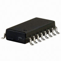
4800P Series - Thick Film Surface Mounted Medium Body
Features
4814P......................................1.12 watts
4816P......................................1.28 watts
4818P......................................1.44 watts
4820P......................................1.60 watts
Represents total content. Layout may vary.
(.050)
(.025)
Package Power Temp. Derating Curve
Typical Part Marking
Recommended Land Pattern
1.27
Package Power Rating at 70°C
NOTE: Land pattern dimensions are based on
design rules established by the Institute for Inter-
connecting and Packaging Electronic Circuits in
IPC-SM-782.
.63
Standard E.I.A. package compatible with
automatic placement equipment
Tape and reel packaging standard
(see page 304 for dimensions)
For ordering guidelines, see page 304
Marking on contrasting background for
permanent identification
1.6
1.4
1.2
1.0
.8
.6
.4
.2
TYP.
TYP.
RESISTANCE
CODE
0
PIN ONE
INDICATOR
4814P
4816P
25
4818P
1
2
3
4
5
6
7
8
9
10 11
AMBIENT TEMPERATURE ( C )
(.350)
8.9
4820P
(.079)
4816P-1
20
19
18
17
16
15
14
13
12
-330
2.0
YYWW
MANUFACTURER'S
TRADEMARK
TYP.
70
SOM-14
(.325)
8.26
(.193)
4.9
CIRCUIT
DATE CODE
PART NUMBER
SOM-16 SOM-18
(.375)
9.53
(.425)
10.80
125
SOM-20
(.475)
12.07
Lead coplanarity .102mm (.004 inch) max. at mounting surface.
Governing dimensions are in metric. Dimensions in parentheses
are inches and are approximate.
*Terminal centerline to centerline measurements made at point of
emergence of the lead from the body.
Product Dimensions
Compliant leads to reduce solder joint
fatiguing
Standard electrical schematics: isolated,
bussed, dual terminator
Custom circuits are available
Specifications are subject to change without notice.
(.024 .004)
R = .008" TYP.
(.080 .005)
.611 .101
2.03 .12
(.490 .005)
(.300 .010)
(.390 .005)
12.45 .12
8 MAX.
7.62 .25
9.91 .12
(.005 + .005/ - .000)
(.220 .005)
.13 + .12/ - .00
5.59 .12
(.012 + .000/ - .004)
.305 + .000/ - .101
(.017 .003)
(.050 .003*)
.432 .076
1.27 .076
(.440 .005)
(.540 .005)
11.18 .12
13.72 .12
TYP.
TYP.