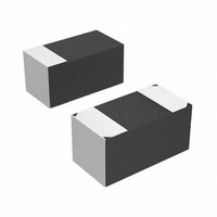
TR8M226M6R3C1500 Vishay, TR8M226M6R3C1500 Datasheet - Page 4

TR8M226M6R3C1500
Manufacturer Part Number
TR8M226M6R3C1500
Description
CAP TANT 22UF 6.3V 20% 0603
Manufacturer
Vishay
Series
MICROTAN™ TR8r
Type
Moldedr
Datasheet
1.TR8M105M016C9500.pdf
(9 pages)
Specifications of TR8M226M6R3C1500
Capacitance
22µF
Voltage - Rated
6.3V
Tolerance
±20%
Esr (equivalent Series Resistance)
1.500 Ohm
Operating Temperature
-55°C ~ 125°C
Mounting Type
Surface Mount
Package / Case
0603 (1608 Metric)
Size / Dimension
0.063" L x 0.033" W (1.60mm x 0.85mm)
Height
0.032" (0.80mm)
Manufacturer Size Code
M
Features
General Purpose
Voltage Rating
6.3 Volts
Operating Temperature Range
- 55 C to + 85 C
Dimensions
0.85 mm W x 1.6 mm L
Product
Tantalum Solid Low ESR Standard Grade
Termination Style
SMD/SMT
Lead Free Status / RoHS Status
Lead free / RoHS Compliant
Lead Spacing
-
Lead Free Status / Rohs Status
Details
Other names
718-1671-2
Document Number: 40114
Revision: 14-Jan-11
ENVIRONMENTAL PERFORMANCE CHARACTERISTICS
ITEM
Life Test at + 85 °C
Humidity Tests
Thermal Shock
MECHANICAL PERFORMANCE CHARACTERISTICS
TEST CONDITION
Terminal Strength
Substrate Bending
(Board flex)
Vibration
Shock
Resistance to Solder
Heat
Solderability
Resistance to
Solvents
Flammability
CONDITION
1000 hours application of rated voltage at
85 °C with a 3 series resistance,
MIL-STD 202G Method 108A
At 40 °C/90 % RH 500 hours, no voltage
applied. MIL-STD 202G Method 103B
At - 55 °C/+ 125 °C, 30 minutes each,
for 5 cycles. MIL-STD 202G Method 107G
CONDITION
Apply a pressure load of 5 N for 10 ± 1 seconds
horizontally to the center of capacitor side body.
AEC-Q200 rev. C Method 006
With parts soldered onto substrate test board,
apply force to the test board for a deflection
of 1 mm. AEC-Q200 rev. C Method 005
MIL-STD-202G, Method 204D,
10 Hz to 2000 Hz, 20 g Peak
Mil-Std-202G, Method 213B, Condition I,
100 g Peak
At 260 °C, for 10 seconds, reflow
MIL-STD-202G, Method 208H, ANSI/J-STD-002,
Test B. Applies only to Solder and tin plated
terminations. Does not apply to gold terminations.
MIL-STD-202, Method 215D
Encapsulation materials meet UL 94 V-0 with an
oxygen index of 32 %.
M
ICRO
T
Solid Tantalum Chip Capacitors
For technical questions, contact:
AN
™ Low ESR, Leadframeless Molded
tantalum@vishay.com
POST TEST PERFORMANCE
Capacitance Change
Dissipation Factor
Leakage Current
Capacitance Change
Dissipation Factor
Leakage Current
Capacitance Change
Dissipation Factor
Leakage Current
POST TEST PERFORMANCE
Capacitance Change
Dissipation Factor
Leakage Current
There shall be no mechanical or visual damage to capacitors
post-conditioning.
Capacitance Change
Dissipation Factor
Leakage Current
Capacitance Change
Dissipation Factor
Leakage Current
There shall be no mechanical or visual damage to capacitors
post-conditioning.
Capacitance Change
Dissipation Factor
Leakage Current
There shall be no mechanical or visual damage to capacitors
post-conditioning.
Capacitance Change
Dissipation Factor
Leakage Current
There shall be no mechanical or visual damage to capacitors
post-conditioning.
There shall be no mechanical or visual damage to capacitors
post-conditioning.
There shall be no mechanical or visual damage to capacitors
post-conditioning.
Refer to Standard Ratings Table
Not to exceed 150 % of initial
Not to exceed 200 % of initial
Refer to Standard Ratings Table
Not to exceed 150 % of initial
Not to exceed 200 % of initial
Refer to Standard Ratings Table
Not to exceed 150 % of initial
Not to exceed 200 % of initial
Refer to Standard Ratings Table
Initial specified value or less
Initial specified value or less
Refer to Standard Ratings Table
Initial specified value or less
Initial specified value or less
Refer to Standard Ratings Table
Initial specified value or less
Initial specified value or less
Refer to Standard Ratings Table
Initial specified value or less
Initial specified value or less
Refer to Standard Ratings Table
Not to exceed 150 % of initial
Not to exceed 200 % of initial
Vishay Sprague
www.vishay.com
TR8
41


