VSSR1603103JUF Vishay, VSSR1603103JUF Datasheet
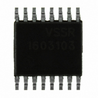
RES NET 10K OHM 16P 8RES QSOP

VSSR1603103JUF

Manufacturer Part Number
VSSR1603103JUF
Description
RES NET 10K OHM 16P 8RES QSOP
Manufacturer
Vishay
Series
VSSRr
Datasheets

Specifications of VSSR1603103JUF

Resistance
10 KOhms
Power Rating
0.1 Watt (1/10 Watt)
Voltage Rating
50 Volts
Temperature Coefficient
±100ppm/°C
Resistance (ohms)
10K
Number Of Resistors
8
Circuit Type
Isolated
Tolerance
±5%
Power Per Element
100mW
Number Of Pins
16
Package / Case
16-LSSOP (0.154", 3.91mm Width)
Size / Dimension
0.193" L x 0.154" W (4.90mm x 3.91mm)
Height
0.064" (1.63mm)
Mounting Type
Surface Mount
Operating Temperature
-55°C ~ 125°C
Product Type
Networks
Operating Temperature Range
- 55 C to + 125 C
Dimensions
3.91 mm W x 4.9 mm L x 1.63 mm H
Lead Spacing
0.64 mm
Termination Style
SMD/SMT
Body Material
Molded Epoxy
Resistance Tolerance
± 5%
No. Of Elements
8
Termination Type
SMD
Lead Free Status / RoHS Status
Lead free / RoHS Compliant
Lead Free Status / RoHS Status
Lead free / RoHS Compliant, Lead free / RoHS Compliant
Other names
VSSR16-10K-JI
Vishay Thin Film resistor networks are designed to be used
in either analog or digital circuits. The use of thin film
resistive elements within the network allows you to achieve
an infinite number of very low noise and high stability circuits
for industrial, medical and scientific instrumentation. Vishay
Thin Film resistor networks are packaged in molded plastic
packages with sizes that are recognized throughout the
world. The rugged packaging offers superior environmental
protection and consistent dimensions for ease of placement
with automatic SMT equipment. Vishay Thin Film stocks
many designs and values for off-the-shelf convenience.
With Vishay Thin Film you can depend on quality products
delivered on time with service backing the product.
SCHEMATICS
01 SCHEMATIC
03 SCHEMATIC
Resistance Range:
10 Ω to 47 kΩ
05 SCHEMATIC
47 SCHEMATIC
Document Number: 60003
Revision: 25-Jan-10
Resistance Range:
10 Ω to 47 kΩ
Lead #1
Pin 1
R
2
R
R
1
1
R
R
V
GND
Lead #1
2
2
Lead #1
CC
Dual-In-Line Resistor, Surface Mount Network
R
R
1
1
R
R
2
2
R
R
1
1
R
R
2
2
R
R
1
1
R
R
2
2
Molded, 25 mil or 50 mil Pitch,
R
R
R
2
1
1
R
2
R
R
R
For technical questions, contact:
1
2
1
R
2
R
R
R
1
2
1
R
R
R
Actual Size
1
2
3
FEATURES
• Reduces total assembly costs
• Compatible with automatic surface mounting
• UL 94 V-0 flame resistant
• Thin film tantalum nitride on silicon
• Choice of package sizes: VTSR (TSSOP)
• Moisture sensitivity level 1 (per IPC/JEDEC STD-20C)
• Isolated/bussed/dual terminator/differential terminator
• Compliant to RoHS directive 2002/95/EC
TYPICAL PERFORMANCE
RESISTORS WITH ONE PIN COMMON
The 01 circuit provides nominally equal resistors connected
between a common pin and a discrete PC board pin.
Commonly used in the following applications:
Broad selection of standard values available
ISOLATED RESISTORS
The 03 circuit provides nominally equal resistors isolated
from all others and wired directly across.
Commonly used in the following applications:
Broad selection of standard values available
DUAL-LINE TERMINATOR; PULSE SQUARING
The 05 circuit contains pairs of resistors connected between
ground and a common line. The junctions of these resistor
pairs are connected to the input leads. The 05 circuits are
designed for dual-line termination and pulse squaring.
Standard values are:
VSSR1605:
R
R
DIFFERENTIAL TERMINATOR
The 47 schematic consists of series resistor sections
connected between V
resistors of 2 different resistance values.
Standard values are:
VSSR20 and VTSR20:
R
1
1
1
MOS/ROM pull-up/-down
Open collector pull-up
"Wired OR" pull-up
Power driven pull-up
"Wired OR" pull-up
Power driven pull-up
Powergate pull-up
Line termination
equipment
JEDEC MC-153, VSSR (SSOP or QSOP) JEDEC MS-137,
VSOR (SOIC narrow) JEDEC MS-012
circuits
thinfilm@vishay.com
= 220 Ω, R
= 330 Ω, R
= 270 Ω, R
TOL.
TCR
2
2
2
= 330 Ω
= 470 Ω
= 120 Ω
VTSR, VSSR, VSOR
CC
ABSOLUTE
ABSOLUTE
5, 2, 1
and ground. Each contains 3
100
VSSR2005:
R
R
R
VSSR16 and VTSR16:
R
R
1
1
1
1
1
TTL input pull-down
Digital pulse squaring
TTL unused gate pull-up
High speed parallels pull-up
Long-line impedance
balancing
LED current limiting
ECL output pull-down
TTL input pull-down
= 220 Ω, R
= 220 Ω, R
= 1.5 kΩ, R
= 330 Ω, R
= 330
Vishay Thin Film
Ω
, R
2
2
2
2
2
= 220
TRACKING
= 330 Ω
= 1.8 kΩ
= 150 Ω
www.vishay.com
= 3.3 kΩ
RATIO
NA
NA
Ω
21

Related parts for VSSR1603103JUF

VSSR1603103JUF Summary of contents

Page 1

... Molded, 25 mil or 50 mil Pitch, Dual-In-Line Resistor, Surface Mount Network Vishay Thin Film resistor networks are designed to be used in either analog or digital circuits. The use of thin film resistive elements within the network allows you to achieve an infinite number of very low noise and high stability circuits for industrial, medical and scientific instrumentation ...

Page 2

... VTSR, VSSR, VSOR Vishay Thin Film Dual-In-Line Resistor, Surface Mount Network STANDARD ELECTRICAL SPECIFICATIONS TEST Material Pin/Lead Number Resistance Range TCR: Absolute TCR: Tracking Tolerance: Absolute Tolerance: Ratio Power Rating: Resistor Power Rating: Package Stability: Absolute Stability: Ratio Voltage Coefficient Working Voltage ...

Page 3

... First 2 digits are significant figures. Last digit specifies number of zeros. 01 102 SCHEMATIC RESISTANCE For technical questions, contact: thinfilm@vishay.com VTSR, VSSR, VSOR Vishay Thin Film Tantalum nitride Silicon Molded epoxy Copper alloy 100 % matte tin 0.0005" 100 ...

Page 4

... Vishay product could result in personal injury or death. Customers using or selling Vishay products not expressly indicated for use in such applications their own risk and agree to fully indemnify and hold Vishay and its distributors harmless from and against any and all claims, liabilities, expenses and damages arising or resulting in connection with such use or sale, including attorneys fees, even if such claim alleges that Vishay or its distributor was negligent regarding the design or manufacture of the part ...

Related keywords