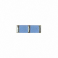
Y1685V0001TT9W Vishay, Y1685V0001TT9W Datasheet - Page 3

Y1685V0001TT9W
Manufacturer Part Number
Y1685V0001TT9W
Description
RES DIV 10K/10K .01% FOIL SMD
Manufacturer
Vishay
Series
VFCD1505r
Datasheet
1.Y1685V0005TT9W.pdf
(4 pages)
Specifications of Y1685V0001TT9W
Resistance (ohms)
10K
Number Of Resistors
2
Circuit Type
Common
Temperature Coefficient
±0.2ppm/°C
Tolerance
±0.01%
Power Per Element
100mW
Number Of Pins
3
Package / Case
1505 (3813 Metric)
Size / Dimension
0.150" L x 0.050" W (3.81mm x 1.27mm)
Height
0.025" (0.64mm)
Mounting Type
Surface Mount
Operating Temperature
-55°C ~ 125°C
Lead Free Status / RoHS Status
Lead free / RoHS Compliant
Other names
VFCD1505 10KOHM/10KOHM ABS. 0.01% MATCH 0.01% S
Y1685-10K/10K
Y1685-10K/10K
Notes
(1)
(2)
Document Number: 63109
Revision: 25-Mar-10
Interloop Capacitance
Reduction in Series
FIGURE 4 - TRIMMING TO VALUES
TABLE 3 - GLOBAL PART NUMBER INFORMATION
NEW GLOBAL PART NUMBER: Y1685V0001QQ9R (preferred part number format)
FOR EXAMPLE: ABOVE GLOBAL ORDER Y1685 V0001 Q Q 9 R:
TYPE: VFCD1505
VALUES: 10K/10K
ABSOLUTE TOLERANCE: ± 0.02 %
TOLERANCE MATCH: 0.02 %
TERMINATION: lead (Pb)-free
PACKAGING: tape and reel
HISTORICAL PART NUMBER: VFCD1505 10K/10K TCR0.2 Q Q S T (will continue to be used)
Application engineering release: for non-standard requests, please contact application engineering
For examples of VCODES see table 1
VFCD1505
VFCD1505
Mutual Inductance
Reduction due
to Opposing
Current in
Adjacent Lines
MODEL
DENOTES PRECISION
Y
1685 = VFCD1505
PRODUCT CODE
Y
(conceptual illustration)
OHMIC VALUE
1
Note: Foil shown in black, etched spaces in white
R
R
10K/10K
1
2
= 10 k
= 10 k
6
CHARACTERISTIC
8
After Trimming
Current Path
TCR0.2
TCR
RESISTANCE
VALUE CODE
from Shorting Strip Area
Changing Current Path
5
Removes this Material
For any questions, contact:
VCODE
Trimming Process
and Increasing
Resistance
Before Trimming
Current Path
ABSOLUTE TOLERANCE
(2)
V
TOLERANCE
T = ± 0.01 %
Q = ± 0.02 %
A = ± 0.05 %
B = ± 0.1 %
C = ± 0.25 %
D = ± 0.5 %
F = ± 1.0 %
ABSOLUTE
T = ± 0.01 %
Q = ± 0.02 %
A = ± 0.05 %
B = ± 0.1 %
C = ± 0.25 %
D = ± 0.5 %
F = ± 1.0 %
0
Q
0
foil@vishaypg.com
FIGURE 5 - TYPICAL RESISTANCE/
TOLERANCE MATCH
(1)
(ppm)
DR
R
TOLERANCE
T = 0.01 %
Q = 0.02 %
A = 0.05 %
+ 500
+ 400
+ 300
+ 200
+ 100
T = 0.01 %
Q = 0.02 %
A = 0.05 %
- 100
- 200
- 300
- 400
- 500
0
MATCH
0
Q
- 55
0 = standard product, tin/lead terminations
9 = standard product, lead (Pb)-free terminations
Other = custom
1
TEMPERATURE CURVE
(for more details see table 1)
- 0.16 ppm/°C
- 25
- 0.1 ppm/°C
S = lead (Pb)-free
B = tin/lead alloy
TERMINATION
Q
VFCD1505 (Z-Foil)
Ambient Temperature (°C)
0
Vishay Foil Resistors
CHARACTERISTICS
0.05 ppm/°C
S
+ 25
Q
0.1 ppm/°C
0.14 ppm/°C
R = tape and reel
W = waffle pack
+ 60 + 75
PACKAGING
0.2 ppm/°C
www.foilresistors.com
9
T = tape and reel
W = waffle pack
PACKAGING
+ 100 + 125
R
T
3


