FLUKE-9040 Fluke Electronics, FLUKE-9040 Datasheet - Page 11
FLUKE-9040
Manufacturer Part Number
FLUKE-9040
Description
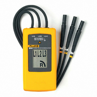
PHASE SEQUENCE INDICATOR
Manufacturer
Fluke Electronics
Datasheet
1.FLUKE-9040.pdf
(14 pages)
Specifications of FLUKE-9040
Voltage Range
40 ~ 690V
Size / Dimension
4.900" L x 2.400" W x 1.100" H (124.46mm x 60.96mm x 27.94mm)
Lead Free Status / RoHS Status
Lead free / RoHS Compliant
Other names
2435050


Determine the Rotary Field Direction
To determine the rotary field direction:
1.
2.
3.
4.
Connect the test probes to the end of the test leads.
Connect the test probes to the three mains phases.
The green ON indicator shows that the instrument is ready for testing.
Either the clockwise or counter-clockwise rotary indicator illuminates showing the type
of rotary field direction present.
The rotary indicator lights even if the neutral conductor, N, is connected
instead of L1, L2, or L3. Refer to the back of the 9040 for more information.
The 9040 is powered from the installation under test.
XW Warning
Note
Determine the Rotary Field Direction
Phase Rotation Indicator
7