90759-1 Tyco Electronics, 90759-1 Datasheet - Page 2
90759-1
Manufacturer Part Number
90759-1
Description
PROCRIMPER III W/DIE 18, 20-22
Manufacturer
Tyco Electronics
Series
Pro-Crimper™ III, Mini Universal MATE-N-LOK®r
Type
Crimpersr
Specifications of 90759-1
Tool Type
Hand Crimper
Features
Side Entry, Ratchet
Rohs Compliant
NA
Product
Crimping, Stripping & Cutting Tools & Drills
Lead Free Status / RoHS Status
Not applicable / Not applicable
For Use With/related Products
Rectangular Contacts, 18-22 AWG
For Use With
1-770988-1 - CONN SOCKET 22-18AWG MINI-UMNLA97677 - CONN PIN 18-22AWG M-U MNL 30GOLD170364-4 - CONN PIN 22-18/(2)22AWG MIN-UMNL170366-4 - CONN SOCKET MINI UMNL 18-22AWGA33329 - CONN SOCKET 18-22AWG GOLD CRIMPA32446 - CONN PIN 18-22AWG GOLD CRIMPA32016 - CONN SOCKET 18-22AWG GOLD CRIMPA32015 - CONN PIN 18-22AWG GOLD CRIMPA97690 - CONN SOCKET 18-22AWG GOLD CRIMPA28813 - CONN SOCKET 18-22AWG GOLD CRIMPA28812 - CONN SOCKET 18-22AWG TIN CRIMPA28805 - CONN PIN 18-22AWG GOLD CRIMPA28804 - CONN PIN 18-22AWG TIN CRIMPA97686 - CONN PIN 18-22AWG PRE-TIN M-UMNL170366-1 - CONN SOCKET 18-22AWG TIN M-UMNLA25684 - CONN SOCKET 18-22AWG TIN CRIMPA25687 - CONN PIN 18-22AWG GOLD CRIMPA25683 - CONN PIN 18-22AWG TIN CRIMPA25688 - CONN SOCKET 18-22AWG GOLD CRIMP
Lead Free Status / Rohs Status
Lead free / RoHS Compliant
Other names
90759-1
A25585
A25585


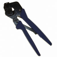
2. DESCRIPTION
The tool features a tool frame with a stationary jaw
and handle, a moving jaw, a moving handle, and an
adjustable ratchet that ensures full contact crimping.
The tool frame holds a die assembly with two
crimping sections.
The die assembly features a wire anvil, an insulation
anvil, a wire crimper, and an insulation crimper.
Attached to the outside of the frame is a locator
assembly, which contains a locator, a spring retainer,
and a contact support.
Die retaining pins and die retaining screws are used
to position and secure the dies in the tool frame. A
nut is used on the upper die retaining screw to hold
the locator assembly in place.
3. INSTALLATION AND REMOVAL OF DIE SET
AND LOCATOR ASSEMBLY
2 of 6
Wire Crimper
1. Open the tool handles and remove the two die
retaining screws from the tool jaws.
2. Place the wire anvil and insulation anvil so that
their chamfered sides and their marked surfaces
face outward, when mounted in the moving jaw of
the tool frame.
3. Insert the two die retaining pins.
4. Insert the short die retaining screw through the
jaw and through both anvil dies, and tighten the
Chamfer
Offset
Wire Anvil
Nut
Locator
(Figures 1 and 2)
Insulation
Anvil
(Figure 2)
Insulation
Crimper
Tyco Electronics Corporation
Chamfer
Locator
Assembly
Figure 2
screw just enough to hold the dies in place. Do not
tighten the screw completely at this time.
5. Place the wire crimper and insulation crimper so
that their chamfered sides and their marked
surfaces face outward, when mounted in the
stationary jaw of the tool frame.
6. Insert the two die retaining pins.
7. Insert the long die retaining screw through the
jaw and through both crimper dies, and tighten the
screw just enough to hold the dies in place. Do not
tighten the screw completely at this time.
8. Carefully close the tool handles, making sure
that the anvils and crimpers align properly.
Continue closing the tool handles until the ratchet
in the tool frame has engaged sufficiently to hold
the anvils and crimpers in place, then tighten both
die retaining screws.
9. Place the locator assembly over the end of the
long screw, and position the locator assembly
against the side of the tool jaw.
10. Place the nut onto the end of the long screw
and tighten the nut enough to hold the locator
assembly in place, while still allowing the locator to
slide up and down.
11. To disassemble, close the tool handles until the
ratchet releases, remove the nut, the locator
assembly, the two die retaining screws, and the
four die retaining pins, and slide the anvils and
crimpers out of the tool jaws.
Die Retaining
Screws
Tool Frame
Die Retaining
Pins
Rev B