58517-4 Tyco Electronics, 58517-4 Datasheet - Page 4
58517-4
Manufacturer Part Number
58517-4
Description
TOOL PRO-CRIMPER II DIE SET
Manufacturer
Tyco Electronics
Datasheet
1.58517-4.pdf
(4 pages)
Specifications of 58517-4
Lead Free Status / RoHS Status
Not applicable / Not applicable


This inspection requires the use of a micrometer with
a modified anvil.
Proceed as follows:
4. If the crimp is still out of alignment, repeat the
adjustment procedure.
1. Refer to Figure 4 and select a wire (maximum
size) for the crimp section.
2. Refer to Section 4, CRIMPING PROCEDURE,
and crimp the contact(s) accordingly.
3. Using a crimp height comparator, measure the
wire barrel crimp height as shown in Figure 4. If the
crimp height conforms to that shown in the table,
the tool is considered dimensionally correct. If not,
i
Tyco Electronics does not manufacture or market
these gages. However, TE recommends the
modified micrometer (Crimp Height Comparator
RS-1019-5LP) .
Figure 4
Figure 5
"
Ensure that the tool and dies are clean by wiping
them with a clean, soft cloth. Remove any debris with
a clean, soft brush. Do not use objects that could
damage the tool. When not in use, keep handles
closed to prevent objects from becoming lodged in
the crimping dies, and store in a clean, dry area.
The crimping dies should be inspected on a regular
basis to ensure that they have not become worn or
damaged. Inspect the crimp section for flattened,
chipped, worn, or broken areas. If damage or
abnormal wear is evident, the tool must be replaced.
See Section 10, REPLACEMENT.
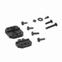
Customer–replaceable parts are shown in Figure 1.
Available separately, PRO–CRIMPER III Hand Tool
Repair Kit 679221–1 includes a replacement nut and
a variety of pins, rings, screws, and springs. If the
dies are damaged or worn excessively, they must be
replaced. Order the repair kit and replaceable parts
through your Tyco Electronics representative, or call
1–800–526–5142, or send a facsimile of your
purchase order to 1–717–986–7605, or write to:
Since the previous release of this sheet, the following
changes were made:
the tool must be adjusted. Refer to Section 7,
CRIMP HEIGHT ADJUSTMENT.
1. Remove the lockscrew from the ratchet
adjustment wheel.
2. With a screwdriver, adjust the ratchet wheel
from the locator side of the tool.
3. Observe the ratchet adjustment wheel. If a
tighter crimp is required, rotate the adjustment
wheel COUNTERCLOCKWISE to a
higher–numbered setting. If a looser crimp is
required, rotate the adjustment wheel
CLOCKWISE to a lower–numbered setting.
4. Replace the lockscrew.
5. Make a sample crimp and measure the crimp
height. If the dimension is acceptable, replace and
secure the lockscrew. If the dimension is
unacceptable, continue to adjust the ratchet, and
again measure a sample crimp.
S TE logo was applied; and
S PRO–CRIMPER II Hand Tool was changed to
PRO–CRIMPER III Hand Tool.