1583696-1 Tyco Electronics, 1583696-1 Datasheet

DIE SET MMCX USE WITH A9996-ND

1583696-1

Manufacturer Part Number
1583696-1
Description
DIE SET MMCX USE WITH A9996-ND
Manufacturer
Tyco Electronics
Series
Pro-Crimper™ IIIr
Datasheet

Specifications of 1583696-1

Connector Type
MMCX, MCX
Crimp Handle
A9996-ND
Product
Tool Component
Lead Free Status / RoHS Status
Not applicable / Not applicable
Crimp Or Cable Size
-
Lead Free Status / Rohs Status
Lead free / RoHS Compliant
Other names
A30731
1. INTRODUCTION
This instruction sheet covers the use and
maintenance of Hex Crimping Die Assembly
1583696–1, which is used in PRO–CRIMPER* II
Hand Tool Frame Assembly 354940–1. The die
assembly crimps various configurations of RF Coaxial
Connectors onto coaxial cable. In this use, the die
assembly provides for the crimping of the center
contact.
PROPER USE GUIDELINES
Cumulative Trauma Disorders can result from the prolonged use of manually powered hand tools. Hand tools are intended for occasional use and low volume
applications. A wide selection of powered application equipment for extended–use, production operations is available.
E
All International Rights Reserved
AMP and Tyco are trademarks. *Trademark
Other products, logos, and company names used are the property of their respective owners.
2003 Tyco Electronics Corporation, Harrisburg, PA
Indenter Die
(Stationary)
Die
Assembly
Figure 1
Tool Jaws
(Ref)
This controlled document is subject to change.
For latest revision, call the FAX/PRODUCT INFO number.
Hex Crimping
Die Assembly
1583696–1
Anvil Die
(Moving)
Figure 2
Tyco Electronics Catalog 1307191 provides a guide
for cable–to–connector selection. For cable sizes and
connectors not referenced in the catalog, contact
Tyco Electronics Product Engineering for connector
recommendations.
Reasons for reissue are provided in Section 7,
REVISION SUMMARY.
2. DESCRIPTION
Each die assembly consists of an indenter die and an
anvil die. When closed, the dies form four crimping
chambers, one of which crimps the center contact
while the remaining three crimp the ferrule of the
connector onto various sizes of coaxial cable. Each
die is held in the tool by a single screw.
3. DIE INSTALLATION
NOTE
1. Close the tool handles until the ratchet releases,
then allow the handles to open fully.
2. Insert the dies into the tool jaws as shown in
Figure 2, and align the retaining holes in each die
with the associated holes in the tool frame.
Dimensions in this instruction sheet are in metric
units [with U.S. customary units in brackets].
Figures are for reference only and are not drawn
to scale.
TOOLING ASSISTANCE CENTER 1–800–722–1111
FAX/PRODUCT INFO 1–800–522–6752
For Regional Customer Service, visit our website at
www.tycoelectronics.com
(Figure 1)
Die
Retaining
Screws
Instruction Sheet
408–8853
11 SEP 03 Rev O
1 of 3
LOC B

1583696-1 Summary of contents

Page 1

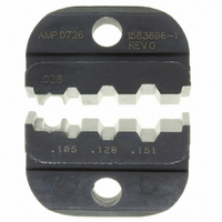
... INTRODUCTION This instruction sheet covers the use and maintenance of Hex Crimping Die Assembly 1583696–1, which is used in PRO–CRIMPER* II Hand Tool Frame Assembly 354940–1. The die assembly crimps various configurations of RF Coaxial Connectors onto coaxial cable. In this use, the die assembly provides for the crimping of the center contact ...

Page 2

... Carefully close the tool handles until the ratchet releases Hex Crimping Die Assembly 1583696–1 8. Allow the tool handles to open fully and remove the crimped connector from the dies. Damaged product must not be used. If damaged CAUTION product is evident, it must be cut from the wire and replaced with a new one ...

Page 3

... If a looser crimp is required, rotate the adjustment wheel CLOCKWISE to a lower–numbered setting. Rev O Hex Crimping Die Assembly 1583696–1 4. Replace the lockscrew. 5. Make a sample crimp and measure the crimp height. If the crimp height is acceptable, secure the lockscrew. If the dimension is unacceptable, remove lockscrew and continue to adjust the ratchet, and again measure a sample crimp ...