58442-1 Tyco Electronics, 58442-1 Datasheet - Page 2
58442-1
Manufacturer Part Number
58442-1
Description
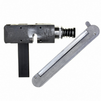
TOOL HEAD ASSEMBLY RCPT MTA 100
Manufacturer
Tyco Electronics
Series
MTA-100r
Type
Hand Toolr
Specifications of 58442-1
Crimp Application
Connectors
Product
Crimping, Stripping & Cutting Tools & Drills
Description/function
Crimp tool assembly for discrete wire MTA-100 receptacles
For Use With
MTA-100 Feed-Through Receptacles
Lead Free Status / RoHS Status
Not applicable / Not applicable
Lead Free Status / RoHS Status
na, Not applicable / Not applicable
Other names
58442-1
A9973
A9973


3. SETUP ADJUSTMENTS AND TEST
The adjuster (insertion rod) of the wire inserter is pre-
set for wire sizes 22 through 28 AWG. If the wire is
being inserted too deeply or not deeply enough inside
the contact, it may be necessary to adjust the air
pressure or the depth of the wire inserter.
3.1. For Electric Power Unit 931800–1
If the wire is inserted too deeply, refer to the proce-
dure in Paragraph 3.3, Wire Insertion Depth
Adjustment.
2 of 4
1. Determine the wire size, and select the
appropriate color–coded connector.
2. Using a small knife, cut off the wire retainers
(strain relief). This will provide a clear view for
inspecting the connector for a properly terminated
wire in the contact. See Figure 2.
3. Place connector in tool and make a test
termination using procedure described in Section
4, TERMINATING PROCEDURE, Steps 1 through
6. If the connector cannot be inserted into the
head, or if the connector is too loose in the head,
loosen the two screws on the insert housing (see
Figure 1) and adjust the insert housing until the
connector fits properly in the head.
4. Push the connector out of the right side of the
head.
5. Inspect termination in accordance with Section
5, INSPECTION, Steps 1 through 6.
Test
Connector
Lock
(Ramp)
Wire Retainer
(Removed)
Lance
MTA Terminating Head 58442–1
Contact (Partially
Removed)
Front Beam
Figure 2
Contact
Slot
3.2. Pistol Grip Pneumatic Handle Assembly 58075–1
and Bench–Mount Power Assembly 58338–1
If the wire is inserted too deeply, refer to the proce-
dure in Paragraph 3.3, Wire Insertion Depth
Adjustment.
3.3. Wire Insertion Depth Adjustment
A. Wire Too Deep
If the wire is inserted too deep in the wire contact slot,
remove the head from the tool, and turn the adjuster
clockwise one–sixth of a revolution. The wire insertion
depth will be reduced by approximately 0.20 [.008].
Repeat the test procedure as described in Paragraph
3.1.
1. Perform the procedure outlined in Paragraph
3.1, For Pistol Grip Manual Handle Assembly,
Steps 1 through 4.
2. Inspect termination to ensure that conductor is
terminated past the lead–in transition and is
positioned about halfway into the contact slot. See
Figure 2.
3. Inspect termination to ensure that insulation is
1.78 to 2.16 [.070 to .085] beyond the front contact
beam.
4. If, upon inspection, it is determined that the wire
is not inserted deeply enough, increase the air
pressure by 69 kPa [10 psi], and repeat the
termination and inspection procedure. Continue in
this manner until either the proper insertion depth
is obtained or the air pressure is set to 483 kPa
[70 psi]. If the proper insertion depth is not reached
at 483 kPa [70 psi], return the air pressure to 276
kPa [40 psi] and follow the procedure in Paragraph
3.3, Wire Insertion Depth Adjustment.
Correct
Production
Connector
Lead–In
Wrong
Deformation
(Figure 3)
Cut in Wire
408–9603
Wrong
Rev A