59827-1 Tyco Electronics, 59827-1 Datasheet
59827-1
Specifications of 59827-1


59827-1 Summary of contents
Page 1
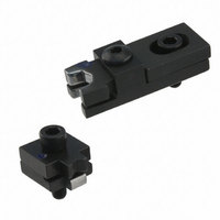
... D Figure 1 This Instruction Sheet (IS) covers the use and care of Crimping Die Assemblies 59826–1, 59827–1, and 59828–1. See Figure 1. These dies are used to crimp the PIDG* and PLASTI–GRIP* FASTON* terminals and splices listed in Figure 2 which are designed to be used in the various applicators and machines listed in Figure 1 ...
Page 2
... Crimping Die Assemblies 59826-1, 59827-1, and 59828-1 Typical PIDG Type Terminals and Splices “C” “B” “C” “B” DIE SET PRODUCT NUMBER NUMBER INSULATION INSULATION AND COLOR AND COLOR COLOR COLOR CODE DOT CODE U Crimp using foot petal control only. ...
Page 3
... Crimping Die Assemblies 59826-1, 59827-1, and 59828-1 ACCEPT 3 2 Wire Range Stamped Here Wire Stop 1 1 Correct product insulation color and die set combination. Wire size is within wire range stamped under terminal 2 tongue or on center of splice. 3 Crimp centered on wire barrel. 4 End of conductor is flush with, or extends slightly beyond end of terminal wire barrel ...
Page 4
... Crimping Die Assemblies 59826-1, 59827-1, and 59828-1 5. CRIMP INSPECTION Inspect crimped terminals and splices by checking the features described in Figure 3. Use only the terminals and splices that meet conditions shown in the “ACCEPT” column. “REJECT” terminals and splices can be avoided through careful use of instructions provided in the ...
Page 5
... Crimping Die Assemblies 59826-1, 59827-1, and 59828-1 Figure 4 A. Wire Barrel Crimp Die Closure 1. Assemble dies so that wire barrel crimp dies are bottomed but not under pressure. Die Closure Configuration DIE CLOSURE DIM'S A" DIE SET DIE SET GO NO-GO { Die closure dimensions apply when wire barrel crimp dies are bottomed but not under pressure. ...
Page 6
... Crimping Die Assemblies 59826-1, 59827-1, and 59828-1 Suggested Plug Gage Design - Insulation Crimp Die Closure Configuration DIE CLOSURE DIM'S D" DIE SET DIE SET GO { Die closure dimensions apply when dies are positioned at gage dimensions as shown in Figure 7B. } Material – Tool Steel Detail A" ...
Page 7
... Crimping Die Assemblies 59826-1, 59827-1, and 59828-1 7. DIE REPLACEMENT AND REPAIR CAUTION Due to their precision design important that no parts of these dies are interchanged. ! Parts listed in Figure 8 are customer–replaceable. A complete inventory can be stocked and controlled to prevent lost time when replacement of parts is necessary ...