59993-1 Tyco Electronics, 59993-1 Datasheet - Page 2
59993-1
Manufacturer Part Number
59993-1
Description
TOOL DIE RG-174/316/188/179/187
Manufacturer
Tyco Electronics
Datasheet
1.59993-1.pdf
(4 pages)
Specifications of 59993-1
Connector Type
Coax Connectors
Crimp Handle
A28006-ND
Crimp Or Cable Size
RG/U-174, 179, 187, 188, 316
For Use With
228596-2 - CONN SOCKET STR SIZE 8 RG179,187228618-2 - CONN PIN STRAIGHT 30AU COAXIAL228618-1 - CONN PIN COAXIAL STRAIGHT GOLD
Lead Free Status / RoHS Status
Not applicable / Not applicable
Other names
A34783


3.2. Ferrule
4. MAINTENANCE AND INSPECTION
The die assembly is inspected before shipment. AMP
recommends that the die assembly be inspected
immediately upon arrival at your facility to ensure that
the die assembly was not damaged during shipment
and that it conforms to the dimensions provided in
Figure 4.
4.1. Daily Maintenance
AMP recommends that each operator of the dies be
made aware of—and responsible for—the following
four steps of daily maintenance:
Front of Tool
(Hand Crimping
Tool 69710–2,
Ref)
Ferrule Shoulder
Against Edge of
Ferrule Crimping
Chamber
2 of 4
1. Slide the ferrule over the cable braid and
contact support sleeve until the ferrule bottoms
against the contact body.
2. Insert contact body through the ferrule crimping
chamber from the FRONT of the tool. Make sure
that the shoulder on the ferrule is against the edge
of the ferrule crimping chamber. See Figure 3.
3. Holding the contact body and ferrule in place,
actuate tool through a complete cycle to crimp the
ferrule.
4. Removed contact assembly from tool.
1. Remove dust, moisture, and other contaminants
with a clean brush or a soft, lint–free cloth. Do
NOT use objects that could damage the dies.
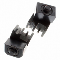
Figure 3
Crimping Die Assembly 59993–1
Ferrule Against
Contact Body
4.2. Periodic Inspection
Regular inspections should be performed by quality
control personnel. A record of scheduled inspections
should remain with the dies and/or be supplied to
supervisory personnel responsible for the dies. The
inspection frequency should be based on the amount
of use, working conditions, operator training and skill,
and established company standards. These
inspections should be performed in the following
sequence:
A. Visual Inspection
4.3. Gaging the Crimping Chamber
This inspection requires the use of plug gages
conforming to the dimensions provided in Figure 4.
AMP does not manufacture or market these gages.
To gage the crimping chamber, proceed as follows:
If the crimping chambers conform to the gage
inspection, the dies may be considered dimensionally
correct and should be lubricated with a THIN coat of
2. Make sure the proper screws are in place and
secured.
3. Make certain all surfaces are protected with a
THIN coat of any good SAE 20 motor oil. Do NOT
oil excessively.
4. When the dies are not in use, store them in a
clean, dry area.
1. Remove all lubrication and accumulated film by
immersing the dies in a suitable commercial
degreaser that will not affect paint or plastic
material.
2. Make certain all screws, retaining rings, and die
components are in place. If replacements are
necessary, refer to parts listed in Figure 4.
3. Check all bearing surfaces for wear. Remove
and replace worn components.
1. Remove traces of oil or dirt from the crimping
chamber and plug gage.
2. Mate the dies until the crimping surfaces have
bottomed; then hold in this position. Do NOT force
beyond initial contact.
3. Insert GO element into the crimping chamber;
but do not force it. The GO element must pass
completely through the crimping chamber. See
Figure 4.
4. In the same manner, try to insert the NO–GO
element into the crimping chamber. The NO–GO
element may enter partially, but must not pass
completely through the length of the crimping
chamber. See Figure 4.
408–6775
Rev A