58436-3 Tyco Electronics, 58436-3 Datasheet - Page 2
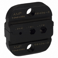
58436-3
Manufacturer Part Number
58436-3
Description
DIESET HEXCRIMP RG174, 179, 180
Manufacturer
Tyco Electronics
Series
Pro-Crimper™ IIIr
Type
Dier
Specifications of 58436-3
Connector Type
BNC, TNC
Crimp Handle
A9996-ND
Crimp Or Cable Size
RG/U-161, 174, 179, 187, 188, 316
Crimp Application
Coaxial
Product
Tool Component
Description/function
BNC Hex Crimp
Features
Die for Pro-Crimper
Fits Cable/wire
161, 174, 179, 179A, 179B, 180, 180A, 187, 187A, 188, 188A, 195, 195A, 316, Belden 9221, C1180B
For Use With
Pro Crimper II Hand Crimp Tool & BNC Crimp Connectors
Lead Free Status / RoHS Status
Not applicable / Not applicable
Lead Free Status / RoHS Status
na, Not applicable / Not applicable
Other names
A9995


Insert Center Contact
into Partially Closed
Crimping Dies
Ferrule
(Ref)
of 3
1. Prepare the connector and the cable according
to the instructions packaged with the connector.
2. Slide the center contact onto the center
conductor of the cable; then insert the contact
assembly into the center contact crimp section of
the die. See Figure 2.
3. Crimp the center contact by holding the cable in
place; then close the tool handles until the ratchet
releases.
1. Insert the crimped center contact into the
connector body until the cable dielectric butts
against the dielectric inside of the connector body.
The flared braid will then fit around the support
sleeve of the connector body.
2. Slide the ferrule forward over the braid until the
ferrule butts against the shoulder on the
connector body.
3. Place the ferrule on the appropriate anvil of the
die assembly so that the shoulder on the connector
body is butted against the die. See Figure 4.
4. Holding the assembly in place, close the tool
handles until the ratchet releases.
i
Make sure that the flange on the end of the
center contact butts against the crimping die. See
Figure 3.
Figure 2
Center Contact
Slipped Over
Center Conductor
Tyco Electronics Corporation
Inspection of the crimping dies should be made on a
regular basis to ensure that they have not become
worn or damaged. Inspect the crimp sections for
flattened, chipped, worn, or broken areas. If damage
or abnormal wear is evident, the dies must be
replaced. Refer to Section 6, PARTS
REPLACEMENT.
Crimping Ferrule
Typical RF
Connector
(Ref)
!
Crimping Die
(Ref)
Flange on End of Center
Contact Butts Against Die
Damaged product should not be used. If a
damaged contact or ferrule is evident, it should
be cut from the wire and replaced with a new
one. Do NOT reterminated contact or ferrules.
Figure 3
Figure 4
Flange on End
of Contact
Ferrule on Anvil
of Crimping Die
Shoulder on
Connector Body
Butts Against Die
Crimping Die
Rev