90391-3 Tyco Electronics, 90391-3 Datasheet

DIE SET ULTRA-FASTONS 16-14 AWG

90391-3

Manufacturer Part Number
90391-3
Description
DIE SET ULTRA-FASTONS 16-14 AWG
Manufacturer
Tyco Electronics
Series
Pro-Crimper™ III, Faston™r
Type
Crimpersr
Datasheets

Specifications of 90391-3

Connector Type
Terminals and Splices
Crimp Handle
A28005-ND
Crimp Or Cable Size
14-16 AWG
Receptacles And Tabs ,tyco Electronics / Amp
ROHS COMPLIANT
Fits Cable/wire
16-14 AWG
Product
Tool Component
Lead Free Status / RoHS Status
Not applicable / Not applicable
For Use With
Platform Hand Tool Frame 58078-3
Lead Free Status / RoHS Status
Not applicable / Not applicable
Other names
90391-3
A28008
PROPER USE GUIDELINES
1. INTRODUCTION
Platform Crimping Die Assemblies 90390–3 and
90391–3 are used in Platform Hand Tool Frame
58078–3 (408–6976). The die assemblies crimp the
Ultra–Fast Fully Insulated FASTON* Terminals listed
in Figure 2. Read These instructions before using the
Platform Hand Tool Frame and Platform Crimping
Dies.
Reasons for reissue are provided in Section 7,
REVISION SUMMARY.
2. DESCRIPTION
Each die assembly consists of an upper die (crimper)
and a lower die (anvil), a retaining screw (on the
upper die), and a hex wrench for securing the lower
die to the platform of the hand tool frame.
The die assemblies are identified by part
numbers,color dot codes, and applicable wire range
designations. See Figure 1. The 90390–3 die
assembly has a red color dot on both the crimper and
the anvil, while the 90391–3 die assembly has a blue
color dot on the crimper and the anvil. The color
E
NOTE
Dimensions are in millimeters [with inch
equivalents in brackets]. Figures are for
identification only and are not drawn to scale.
Figure 1
Crimping Die Assemblies
90390-3 and 90391-3
coding on the die assembly corresponds to the color
coding on translucent insulation of the Ultra–Fast
FASTON terminal for easier identification when
crimping.
3. INSTALLATION
Determine the part number of the terminal you are
crimping, then refer to the table in Figure 2 and select
the appropriate die assembly. Install dies as
described below.
3.1. Installing Lower Die Assembly
3.2. Installing Upper Die Assembly
1. Squeeze the tool handlers together until they
bottom. Then allow them to open fully.
2. Hold the hand tool frame so that the back of the
tool is facing you and note the socket head screw
located in the lower die platform. See Figure 3.
3. Slide the lower die onto the lower platform,
ensuring that the drilled holes on the side of the
lower die line up with the socket head screw.
NOTE
4. With the lower die in place, turn the socket head
screw (on the die platform) clockwise until snug.
Do NOT overtighten.
1. Remove the die retaining screw from the die
assembly.
2. Position the upper die in upper die platform of
the tool. Thread the die retaining screw through the
mounting hole in the top of tool and tighten the
screw until it is snug but NOT secured.
3. While guiding the upper die into alignment with
the lower die, slowly close the tool handles until the
dies bottom.
4. Tighten the upper die retaining screw until the
die is secure.
5. Squeeze the tool handles together until the
ratchet releases. Allow the tool handles to open
fully. The tool is now ready for use.
If the lower die will not seat on the lower die
platform with the drilled hole aligned with the
socket head screw, use the hex wrench to turn
the screw either in or out until the set screw does
not protrude from either side of the lower tool jaw.
www.tycoelectronics.com
408-9279
1

90391-3 Summary of contents

Page 1

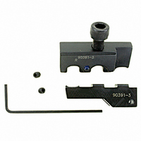
... The color E Crimping Die Assemblies 90390-3 and 90391-3 coding on the die assembly corresponds to the color coding on translucent insulation of the Ultra–Fast FASTON terminal for easier identification when crimping ...

Page 2

... WIRE WIRE SIZE INSUL DIA SERIES (AWG) (Max) 2 Crimping Die Assemblies 90390-3 and 90391-3 TERMINAL TYPE COLOR LP CODE Figure 2 408-9279 DIE STRIP DIE CRIMP NUMBER SYMBOL (Dot Code) B ...

Page 3

... S For in–line terminals, the flat side of the terminal must seat on the locator. B Rev Crimping Die Assemblies 90390-3 and 90391-3 S For flag terminals, the flat side of the wire end Upper Die must face outward and the mating end must seat on the locator. ...

Page 4

... NO–GO element may start entry but must not pass completely through, as shown in Figure Crimping Die Assemblies 90390-3 and 90391-3 If the crimping chamber conforms to the gage inspection, the dies are considered dimensionally correct and should be lubricated with a THIN coat of SAE 20 motor oil. If not, the dies must be repaired before returning them to service ...

Page 5

... PART NUMBER 1 3-21000-4 2 21027-3 B Rev Crimping Die Assemblies 90390-3 and 90391-3 Dies may be returned to Tyco Electronics for evaluation and repair. For tool repair service, contact a Tyco Electronics Representative at 1–800–526–5136. 7. REVISION SUMMARY The following changes were made since the previous ...