318451-2 Tyco Electronics, 318451-2 Datasheet - Page 4
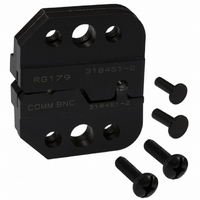
318451-2
Manufacturer Part Number
318451-2
Description
DIE SET
Manufacturer
Tyco Electronics
Series
Pro-Crimper™ IIIr
Type
Crimp Toolr
Specifications of 318451-2
Connector Type
Coax Connectors
Crimp Handle
Tyco/AMP 318451-1
Crimp Or Cable Size
RG/U-79, 161, 187
Features
"O" / Commercial
Crimp Application
Coaxial
Product
Crimping, Stripping & Cutting Tools & Drills
For Use With
75 Ohm BNC RF/Coaxial Connectors
Lead Free Status / RoHS Status
Not applicable / Not applicable
Lead Free Status / RoHS Status
na, Not applicable / Not applicable
Other names
318451-2
A24630
A24630


This inspection requires the use of a plug gage
conforming to the dimensions in Figure 6. Tyco
Electronics does not manufacture or market these
gages. To gage the ferrule crimping chamber,
proceed as follows:
Measuring Center Contact Crimp Height
Suggested Plug Gage for
Ferrule Crimping Chamber
2. Refer to Section 4, CRIMPING PROCEDURE,
and crimp the center contact accordingly.
3. Using a crimp height comparator, measure the
crimp height as shown in Figure 5. If the crimp
height conforms to that shown, the die assembly is
considered dimensionally correct. If not, return the
dies to Tyco Electronics for evaluation and repair
(refer to Section 8, DIE REPLACEMENT).
1. Close the jaws until the dies have bottomed,
then HOLD the frame handles in this position. Do
NOT force the dies beyond initial contact.
2. Align the GO element with the ferrule crimping
chamber. Push the element straight into the
crimping chamber without using force. The GO
Figure 5
Figure 6
The frame assembly ratchet mechanism features an
adjustment wheel with numbered settings. If the crimp
height is not acceptable, adjust the ratchet as follows:
element must pass completely through the
crimping chamber.
3. Align the NO–GO element and try to insert it
straight into the same crimping chamber. The
NO–GO element may start entry, but must not
pass completely through.
4. Repeat Steps 2 and 3 for the insulation ferrule
section of the crimping chamber.
1. Remove the lockscrew from the ratchet
adjustment wheel.
2. With a screwdriver, adjust the ratchet wheel
from the opposite side of the frame.
3. Observe the ratchet adjustment wheel. If a
tighter crimp is required, rotate the adjustment
wheel COUNTERCLOCKWISE to a
higher–numbered setting. If a looser crimp is
required, rotate the adjustment wheel
CLOCKWISE to a lower–numbered setting.
4. Replace the lockscrew.
5. Make a sample crimp and measure the crimp
height. If the crimp height is acceptable, secure the
lockscrew. If the dimension is unacceptable,
remove lockscrew and continue to adjust the
ratchet, and again measure a sample crimp.
i
Insert the gage element for the insulation ferrule
section into the back of the crimping chamber.
The GO element for this section will not pass
completely through the crimping chamber.
Figure 7