58336-1 Tyco Electronics, 58336-1 Datasheet - Page 2
58336-1
Manufacturer Part Number
58336-1
Description
HEAD (IDC) MODU MTE W/O TL
Manufacturer
Tyco Electronics
Series
AMPMODU® MTEr
Type
Amp Tool Kitr
Specifications of 58336-1
Connector Type
Rectangular
Crimp Handle
A2031-ND, 58075-1-ND, 58338-1-ND, 931800-1-ND
Crimp Or Cable Size
22-30 AWG
Product
Tool Component
For Use With
58075-1 - TOOL HANDLE PNEUMATIC W/O HEAD931800-1 - ELEC PWR UNIT W/O F/TRK OR HD58338-1 - PWR BENCH ASSEMBLY W/O HEADS
Lead Free Status / RoHS Status
Not applicable / Not applicable
Lead Free Status / RoHS Status
na, Not applicable / Not applicable
Other names
58336-1
A28718
A28718


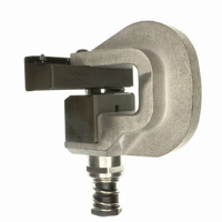
2. DESCRIPTION
The terminating head is designed for use in Manual
Handle Assembly 58074--1 (408--6790), Pneumatic
Handle Assembly 58075--1 (408--6789), Pneumatic
Power Bench Assembly 58338--1 (408--9393), and
the Electric Bench Machine 931800--1 (409--5746).
Note that the pneumatic handle assembly is designed
to operate at air pressure between 276--483 kPa
[40--70 psi].
The head, when installed in either handle assembly,
terminates wires in the single--row AMPMODU MTE
contact housing assemblies listed in Figure 1. Refer
to Instruction Sheet 408--6919 for a complete
description of the AMPMODU MTE Connectors. Note
that even though the head terminates both strip--form
and individual housing assemblies, it does not
terminate individual housing assemblies of less than
six positions.
Wires are terminated using the Insulation
Displacement Technique, which inserts unstripped
wire into a slotted contact beam to form a reliable
electrical connection between the wire and the
contact.
After the head is inserted into the tool handle
assembly, the head serves as a guide for the housing
assemblies during termination. Features of the head
and their functions are as follows:
3. ADJUSTMENTS
3.1. Feed Adjustment
The insulation barrel supports on the contact must be
centered on the wire inserter when the contact is in
2 of 7
Wire Inserter - - forces wire into two slotted beams
of the contact and provides support for the contact
beams when insertion force is applied to the wire.
Adjuster (Insertion Rod) - - is a piston for, and
regulates travel of, the wire inserter.
Feed Pawl - - advances contact carrier strip to the
terminating position.
Feed Arm - - driven by the retraction of the inserter,
the feed arm drives the feed pawl.
Contact Drag - - keeps the contact carrier strip in
the strip guide and prevents the connector from
moving out of position after the feed pawl
advances it.
Guide Strip - - aligns and supports the contact
carrier strip.
Feed Adjustment Screw - - regulates position of
contact relative to the wire inserter.
the terminating position. The feed adjustment screw
regulates the travel of the feed pawl which advances
the contact to the terminating position. Make this
adjustment as follows:
1. Obtain a housing assembly. Refer to the chart in
Figure 1.
2. Squeeze the tool trigger (pneumatic handle
assembly or cam handle (manual handle) and push
the housing assembly against the wire inserter.
3. Release the trigger or cam handle; the housing
assembly will be indexed to the first contact
position.
4. Squeeze the trigger or cam handle until the feed
pawl clicks; then release the trigger or handle. The
housing assembly should have advanced to the
next contact position.
5. Squeeze cam handle until the wire inserter is
partially extended but does not touch the insulation
barrel supports. If using a pneumatic handle
assembly, reduce air pressure to 0 kPa [0 psi],
squeeze the trigger, and increase air pressure until
the wire inserter is partially extended. Refer to
Figure 2.
6. To advance the contact, turn the feed
adjustment screw COUNTERCLOCKWISE. To
back up the contact, turn feed adjustment screw
CLOCKWISE while pulling back on the carrier
strip.
7. Repeat Steps 4 through 6 as necessary.
Feed Pawl
Feed Adjustment Screw
Figure 2
Contact
Wire Inserter
408- 9359
Rev C