597D156X9050R2T Vishay, 597D156X9050R2T Datasheet
597D156X9050R2T
Specifications of 597D156X9050R2T


Related parts for 597D156X9050R2T

597D156X9050R2T Summary of contents
Page 1
... For technical questions, contact: tantalum@vishay.com Vishay Sprague ® , ANTAMOUNT CASE CODE TERMINATION REEL SIZE AND ...
Page 2
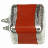
... Solid Tantalum Chip Capacitors T Vishay Sprague Ultra-Low ESR, Conformal Coated, Maximum CV RATINGS AND CASE CODE µ 6 100 150 220 330 V 470 V E 680 E E 1000 E/R R 1500 R STANDARD RATINGS CAPACITANCE CASE CODE PART NUMBER (µF) 470 V 597D477X_004V__ 680 E 597D687X_004E__ 1000 ...
Page 3
... V 'V' CASE SIZE ESR and Z vs. FREQUENCY 10 ESR Z 1 0.1 0.01 100 Hz 100 kHz 1 MHz For technical questions, contact: tantalum@vishay.com 597D ® , Vishay Sprague ESR Z 1 kHz 10 kHz 100 kHz FREQUENCY ESR Z 1 kHz 10 kHz 100 kHz FREQUENCY ESR Z 1 kHz ...
Page 4
... Vishay product could result in personal injury or death. Customers using or selling Vishay products not expressly indicated for use in such applications their own risk and agree to fully indemnify and hold Vishay and its distributors harmless from and against any and all claims, liabilities, expenses and damages arising or resulting in connection with such use or sale, including attorneys fees, even if such claim alleges that Vishay or its distributor was negligent regarding the design or manufacture of the part ...